Compound
Compound
CNC Machined Chair
The constraints for this project were as follows: The chair had to be machined from a single sheet of 4 by 8 foot 3/4” thick plywood with specific tooling the school had on hand. We were limited to single sided machining, and use of outside materials had to be minimal. The project was split into two phases, two weeks to design and two weeks to build.
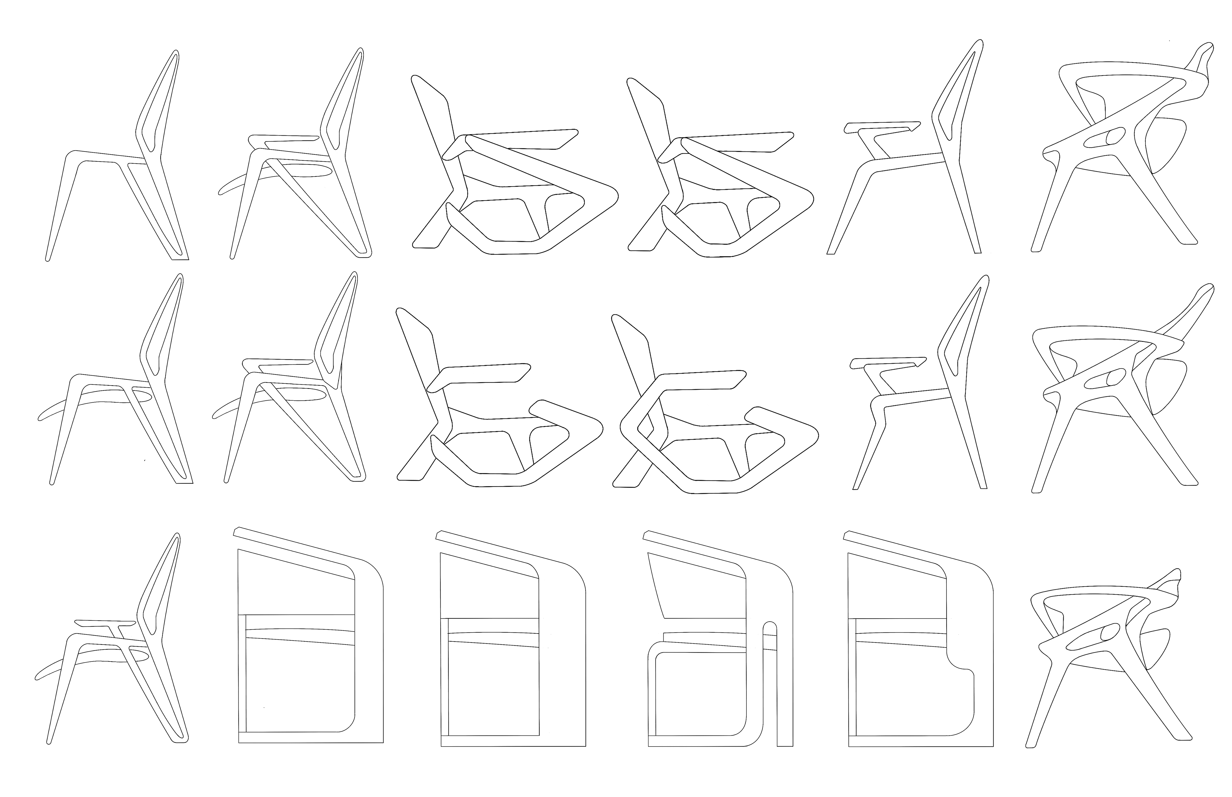

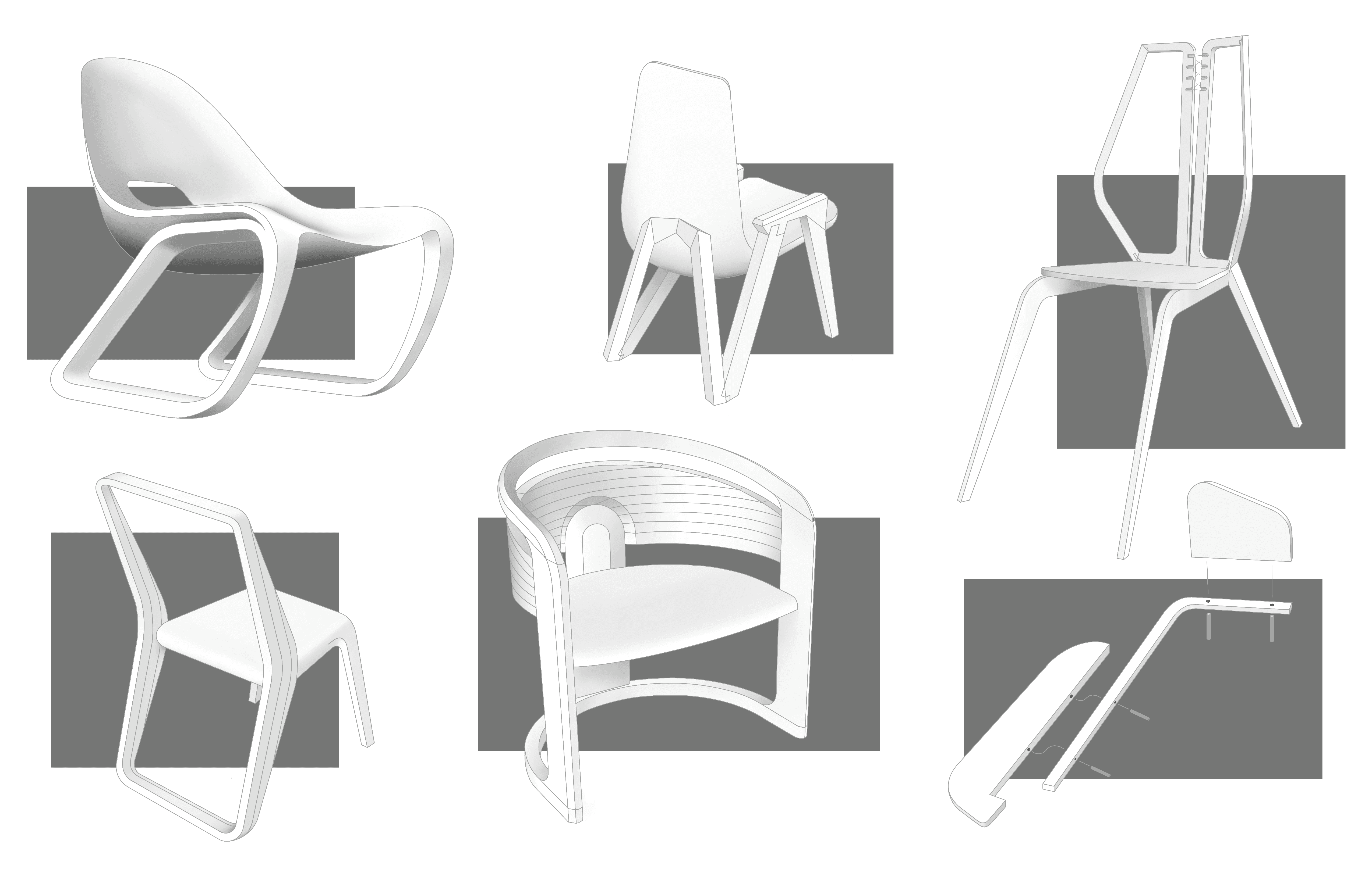

From the start of the project I was determined break free from the typical 90 degree angles and flat panels typically utilized in CNC machined furniture designs. Aside from a unique look, I felt that moving away from a “planar” design could signifigantly improve ergonomics. I also began thinking about joinery, and how to layer my material to achieve certain designs. The prototpes were constructed at material scale, meaning that the models were built with to-scale foamcore thickness relative to the plywood. I paid close attention to ergonomics, studying human anatomy as well as key measurements from several real-life chairs.
Prototypes
Prototypes
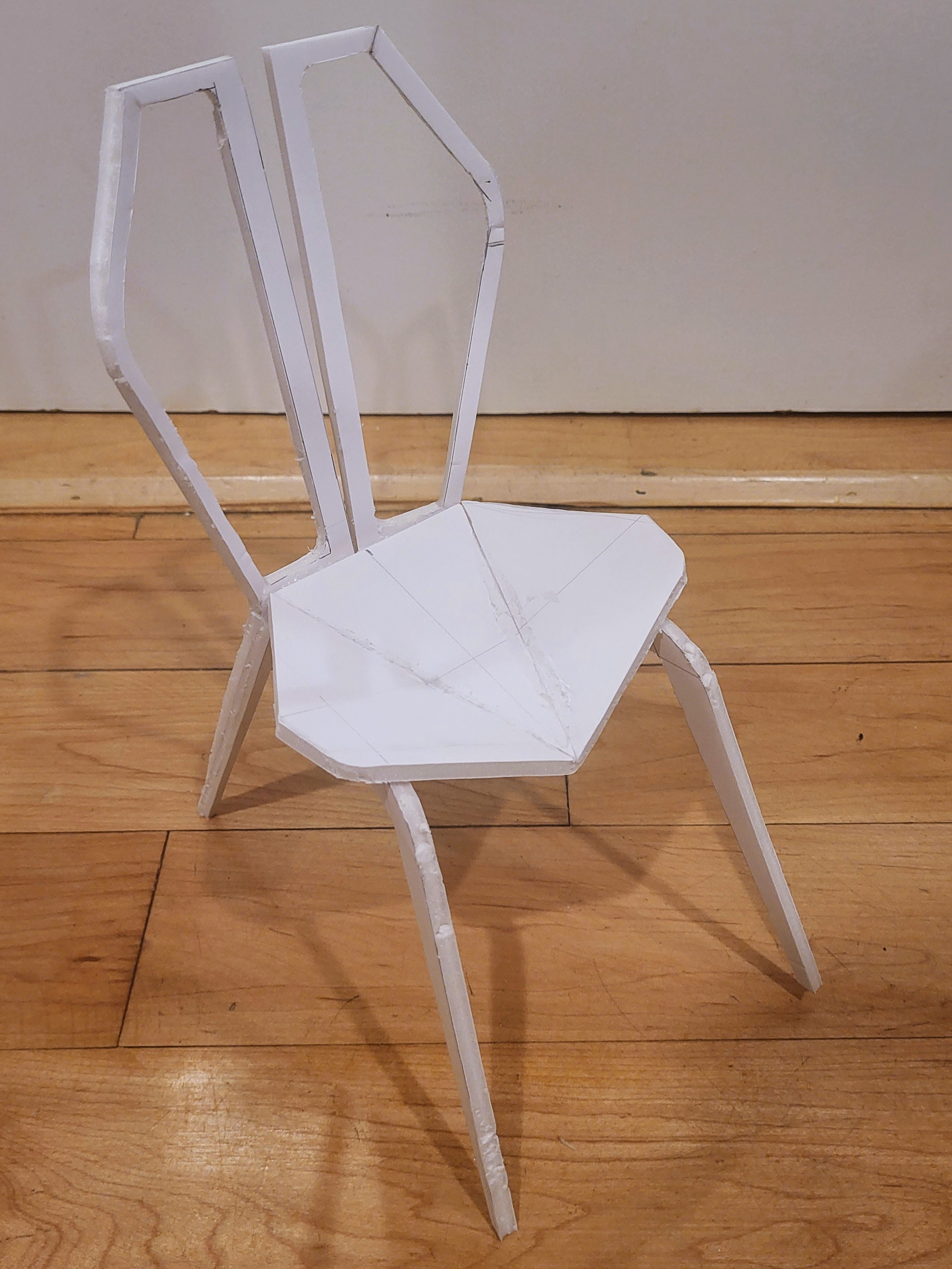


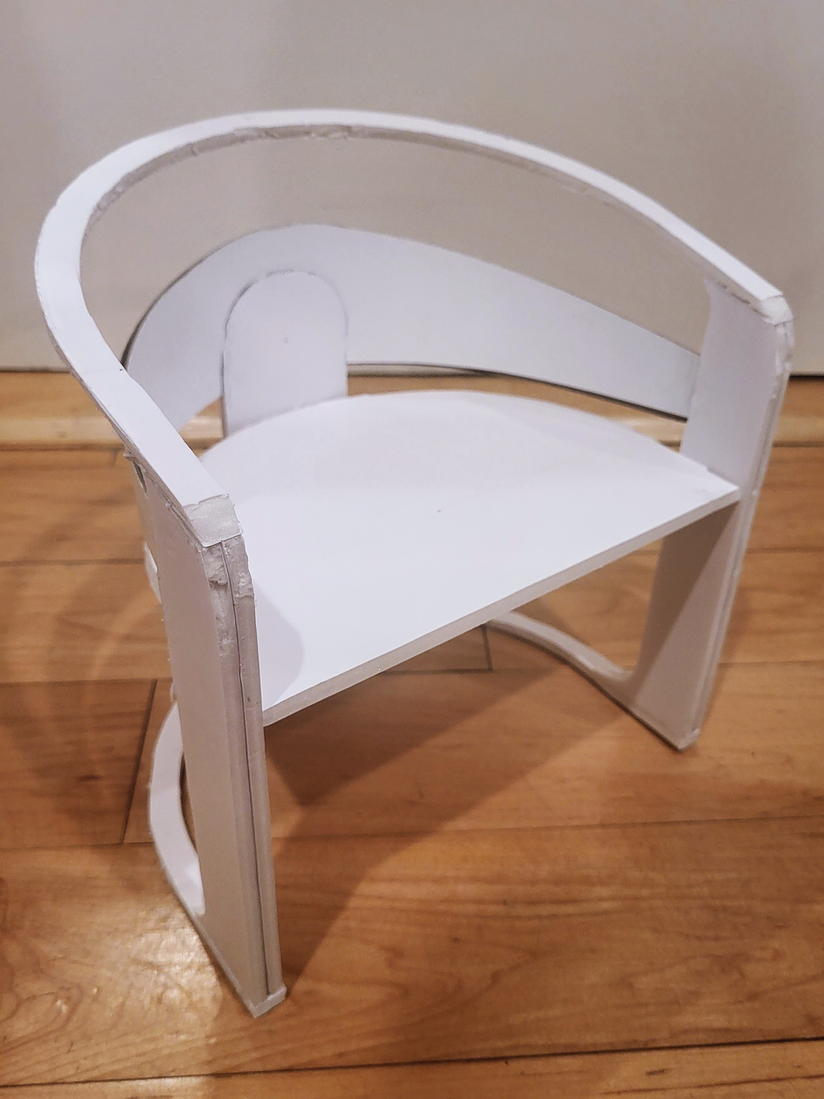


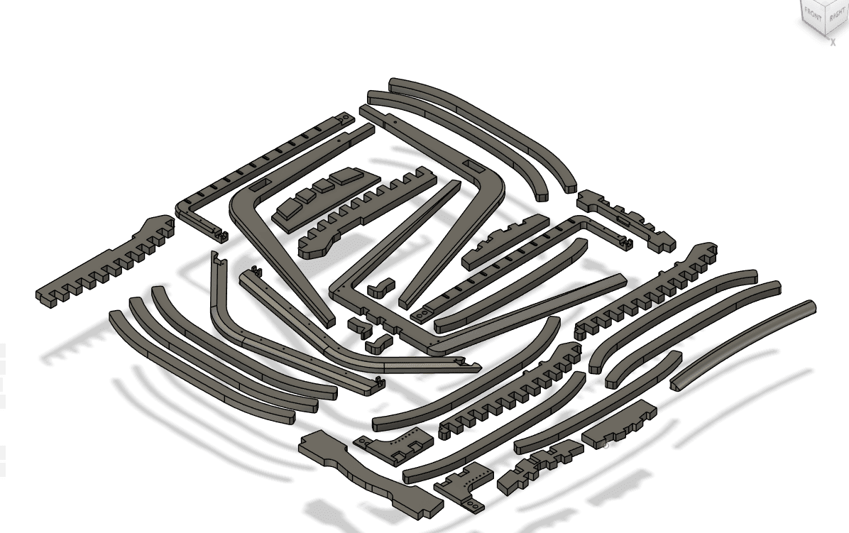
After settling on a design, I moved to 3D modeling in Solidworks. My process was complicated by my design decisions and the limitation of single-sided machining. It became clear that conventional joinery would not be possible for the design. I settled on small 3D printed joinery pieces combined with limited hardware and the use of steel cable. After my model was done, I moved to Fusion360 for CAM programming. During the process, I learned a lot about how to order operations and when to use specific ones.

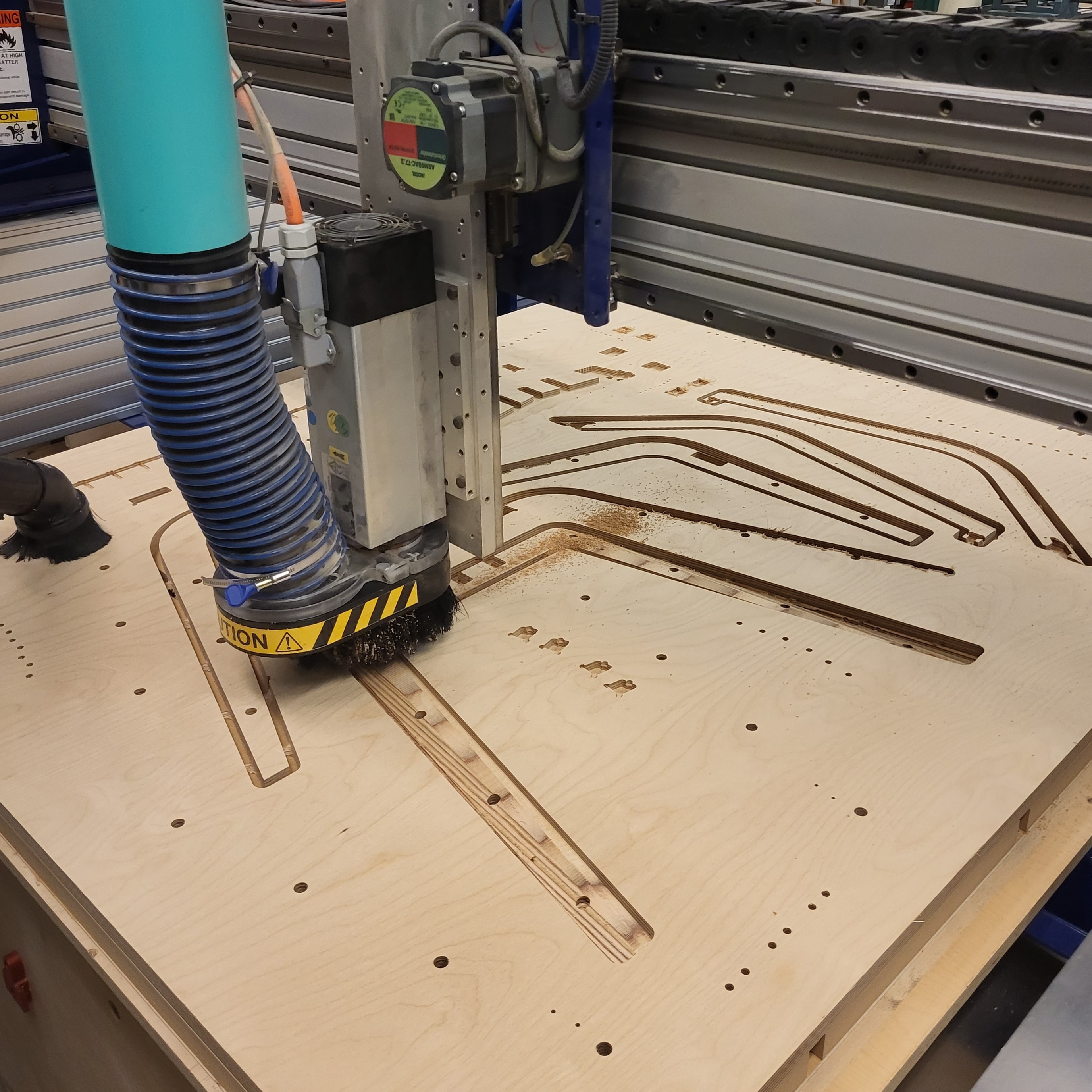
CNC routing of my chair in progress, during a 3D contour operation.
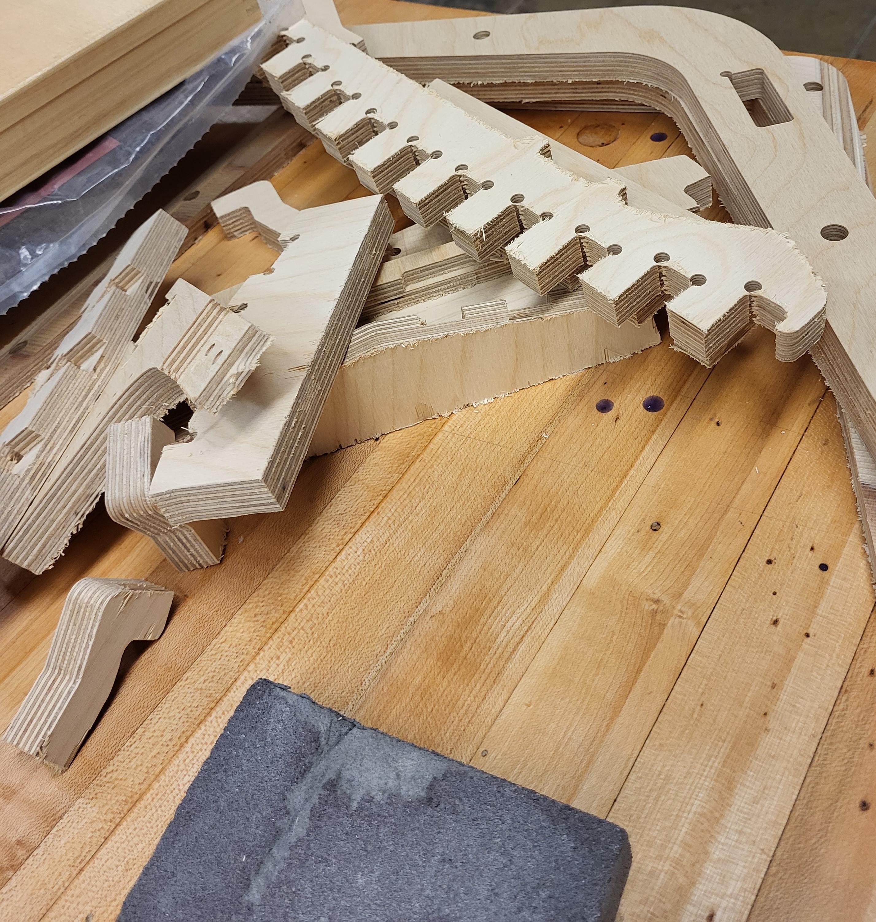
After removal from the stock material, the edges were refined with a sanding sponge.
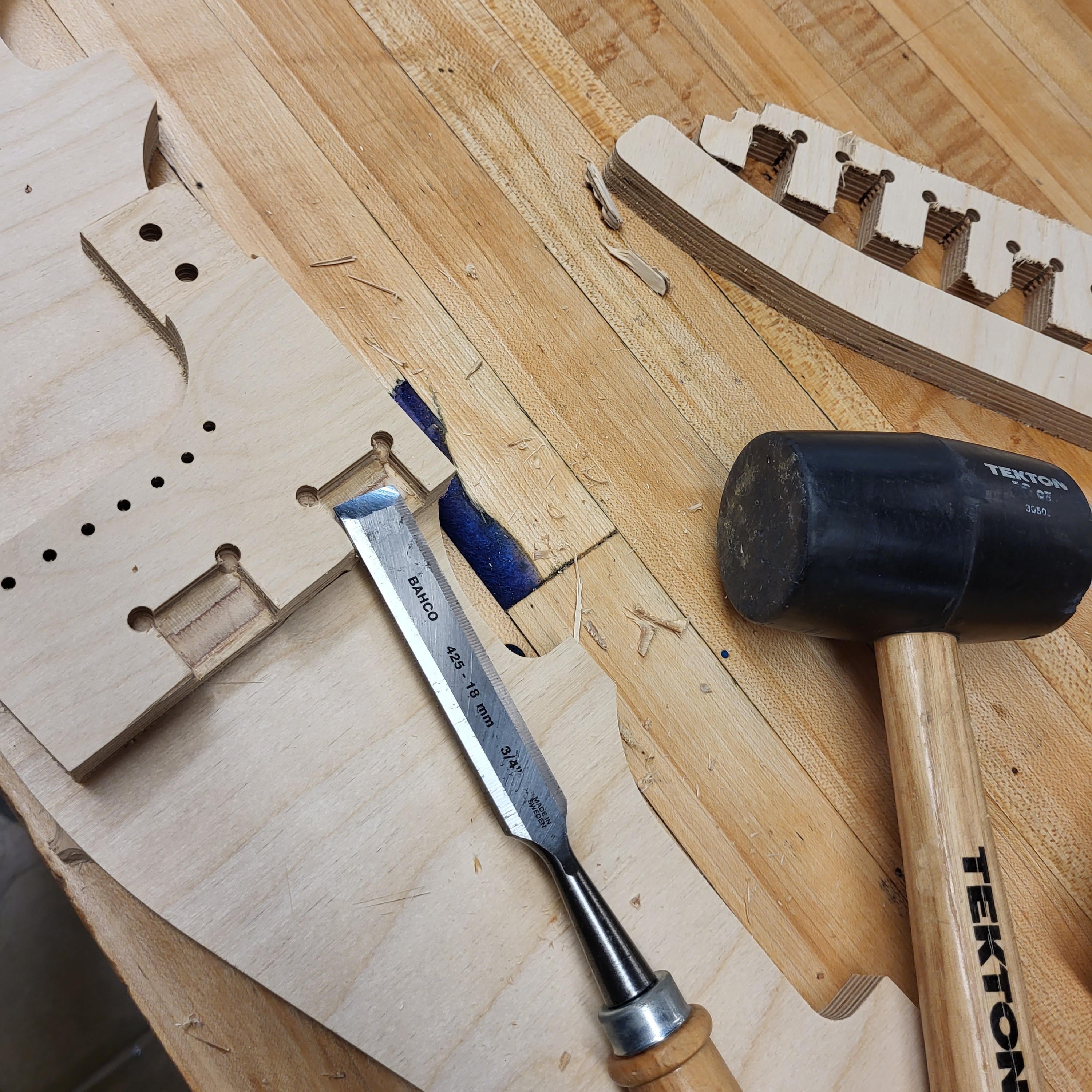
Several parts were designed with minor chisel work in mind. Visible "dogbones" were minimized.
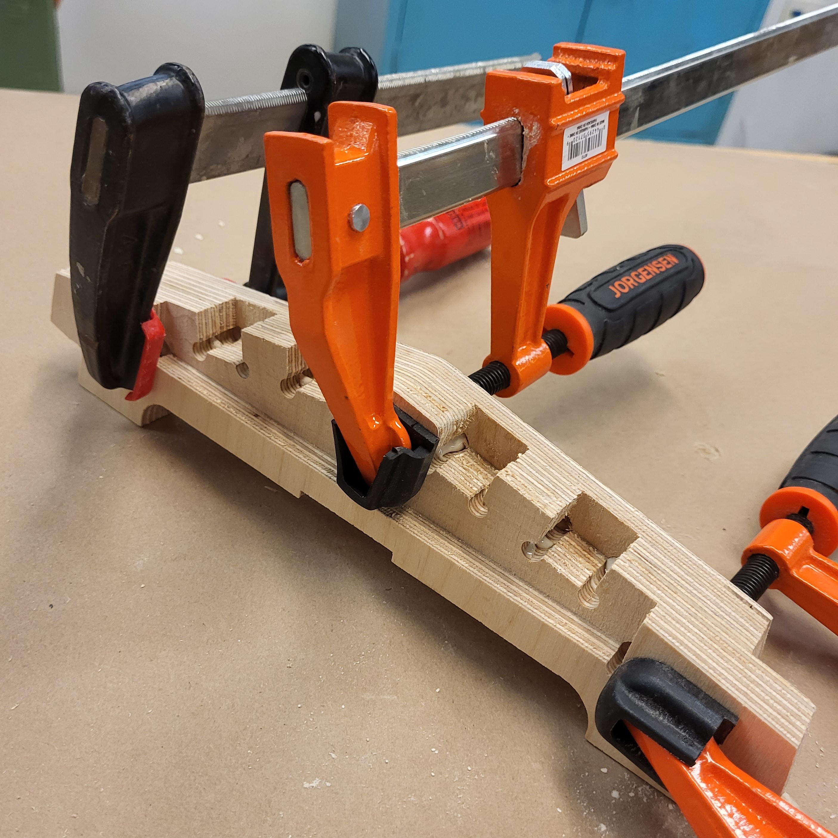
The subframe was greatly complicated by the single-sided machining. All the pieces were glued and clamped across several steps.
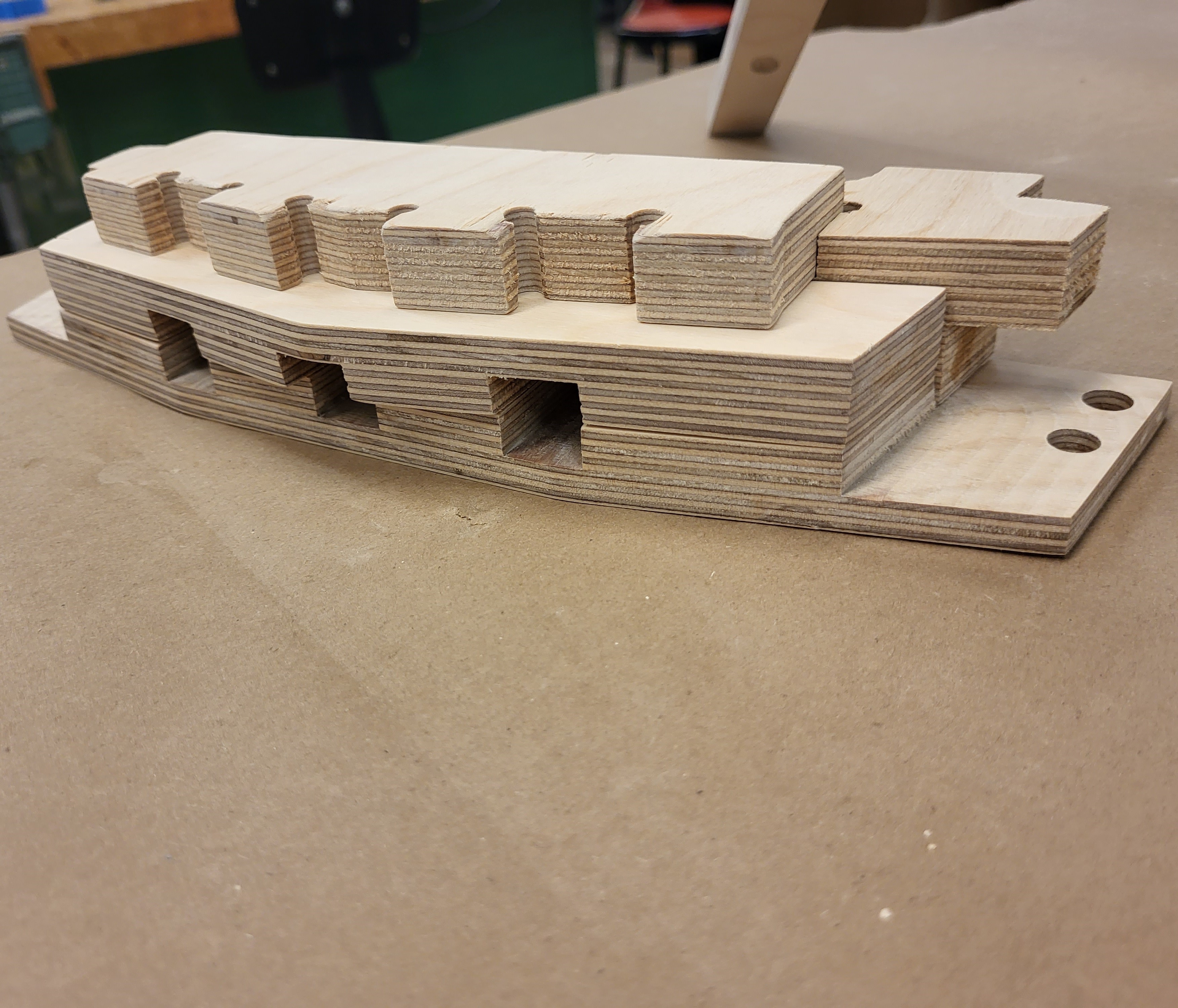
The subframe part connects several parts at various complex angles.
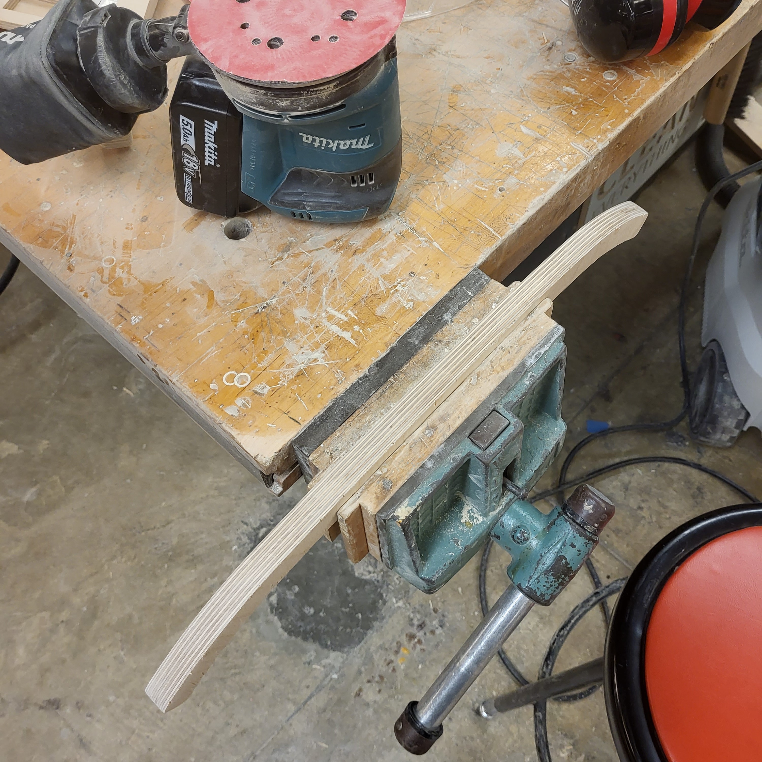
The mill left a rough finish on part edges. Every part was finished to 400 grit in preparation for varnish. Pictured here is a seat slat.
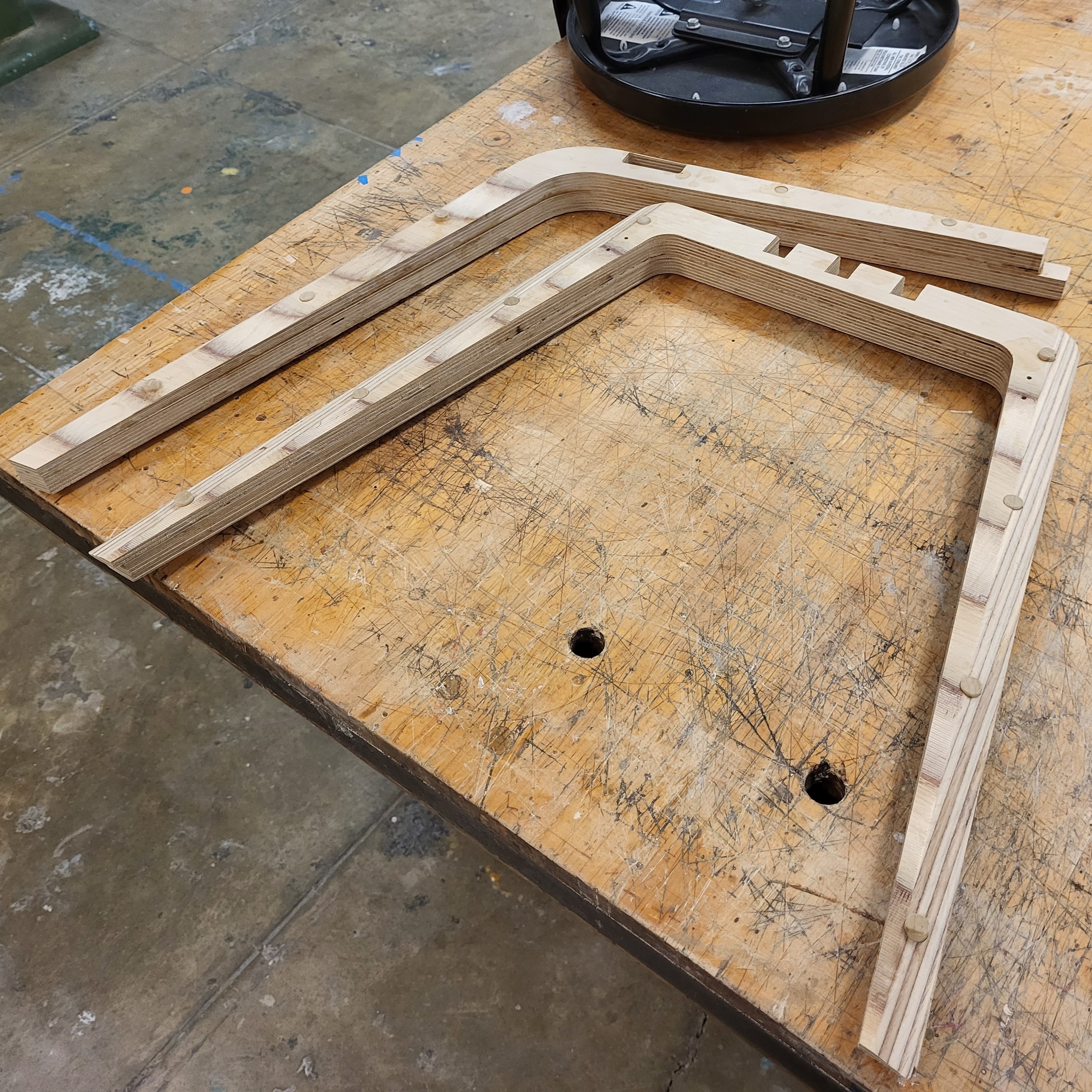
The chair legs are made from two layers of plywood sheet and CNC contoured. I added dowels to stabilize the glued connection.
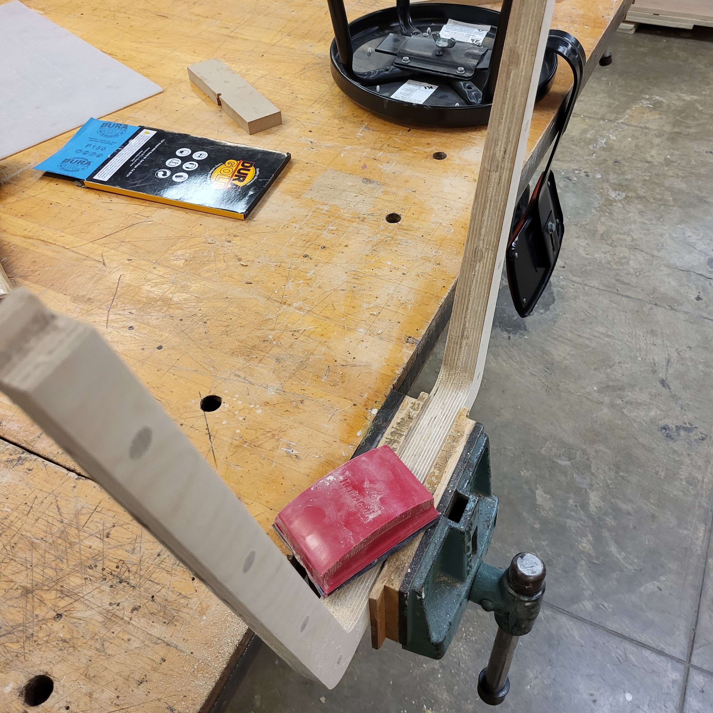
The excess dowels were sawed off and sanded flush, while the two layers were perfectly aligned with sanding.
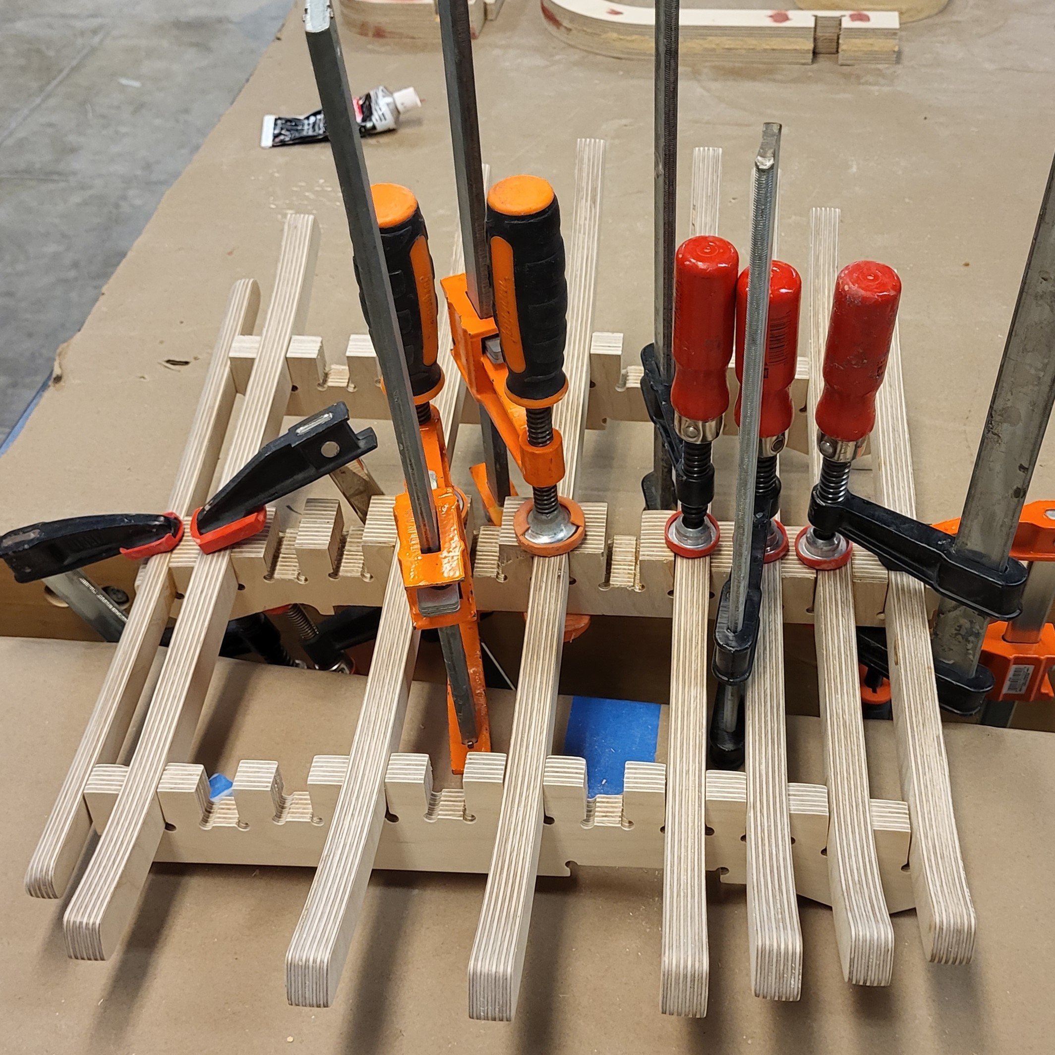
To facilitate clamp placement, the slats had to be glued in multiple steps.
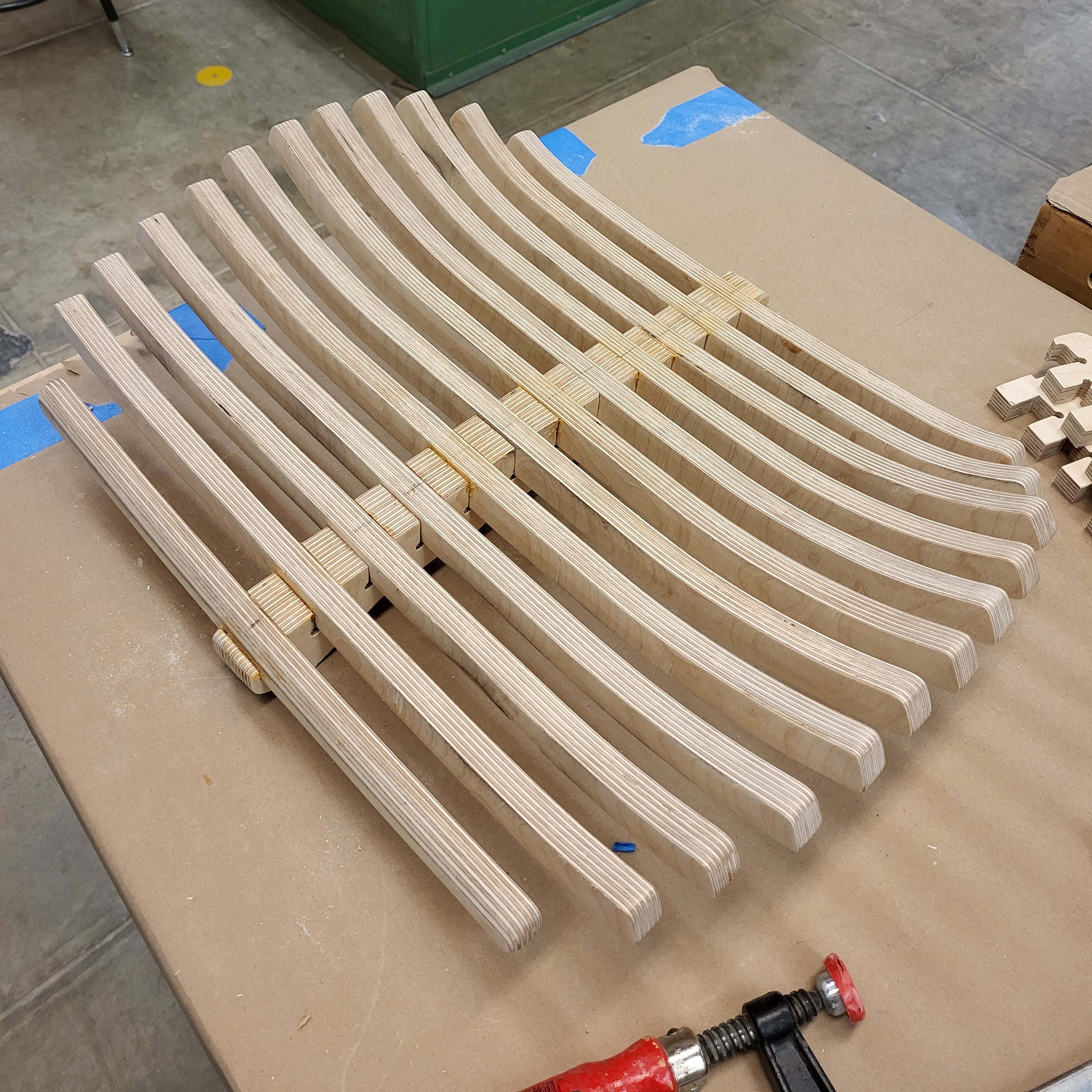
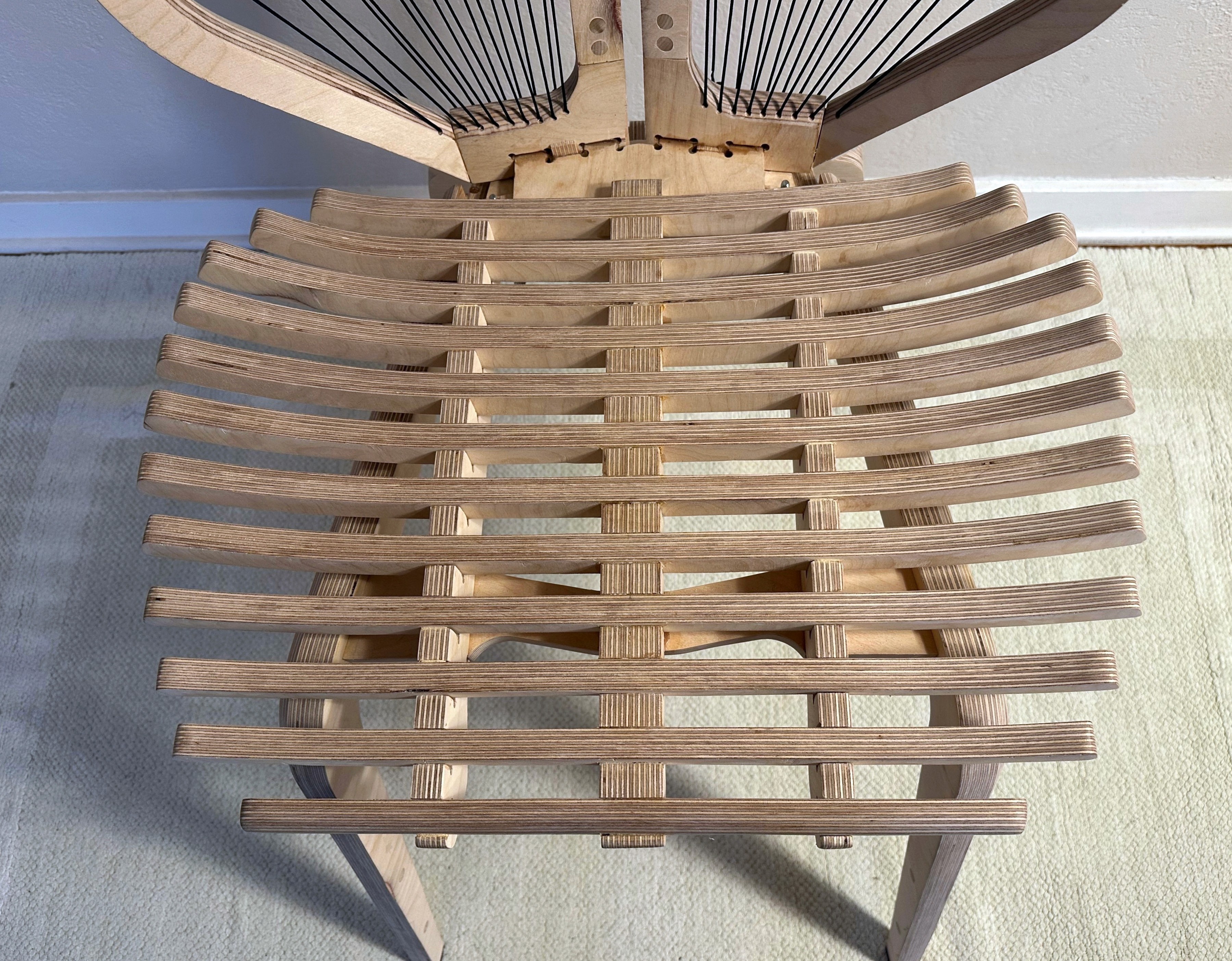
My slat-based design allowed me to create an erogonomic, supportive, organic seat shape. The goal was comfort without any upholstery.
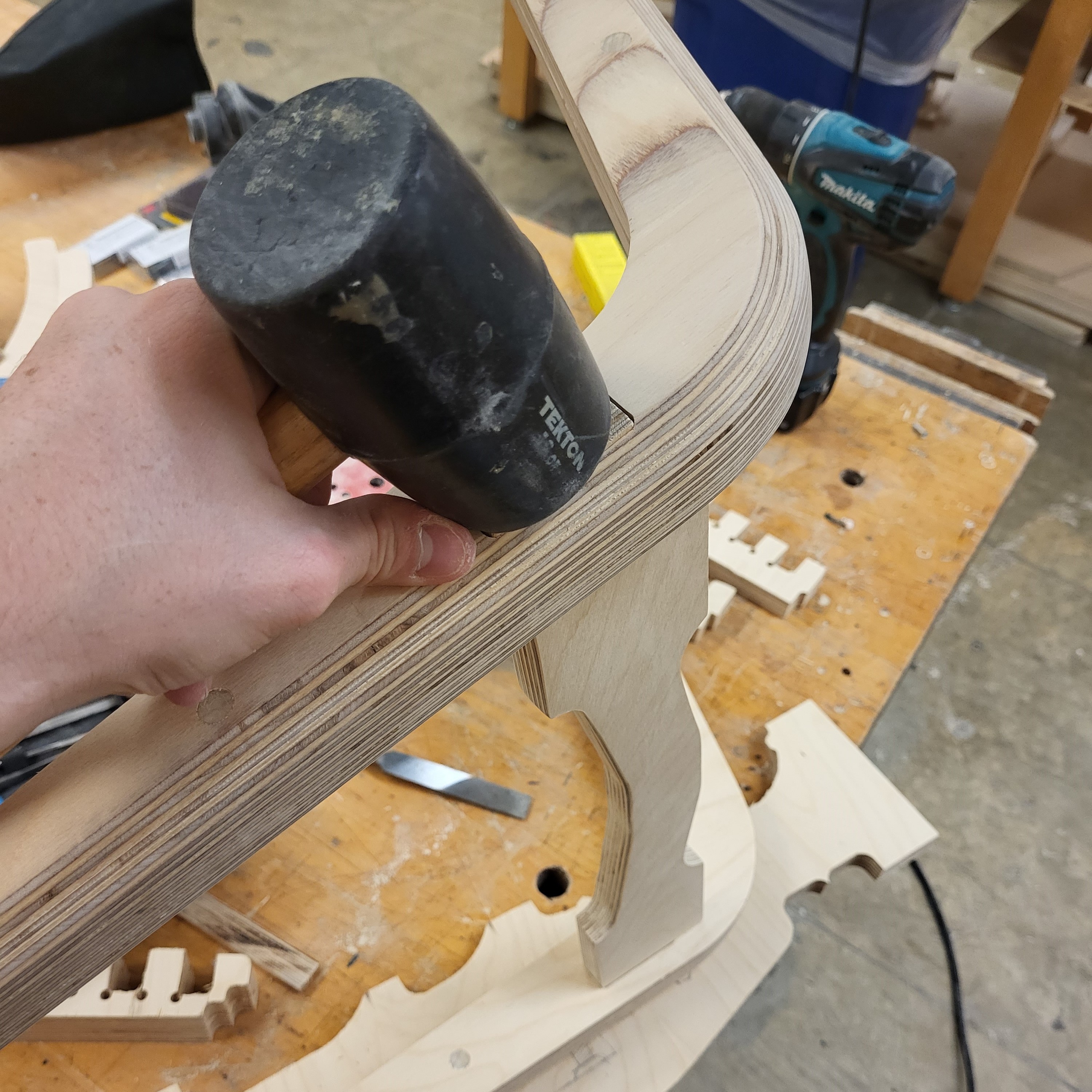
Then the front leg assembly and rear legs were glued into the subframe. The front leg attachment points were stabilized with dowels.
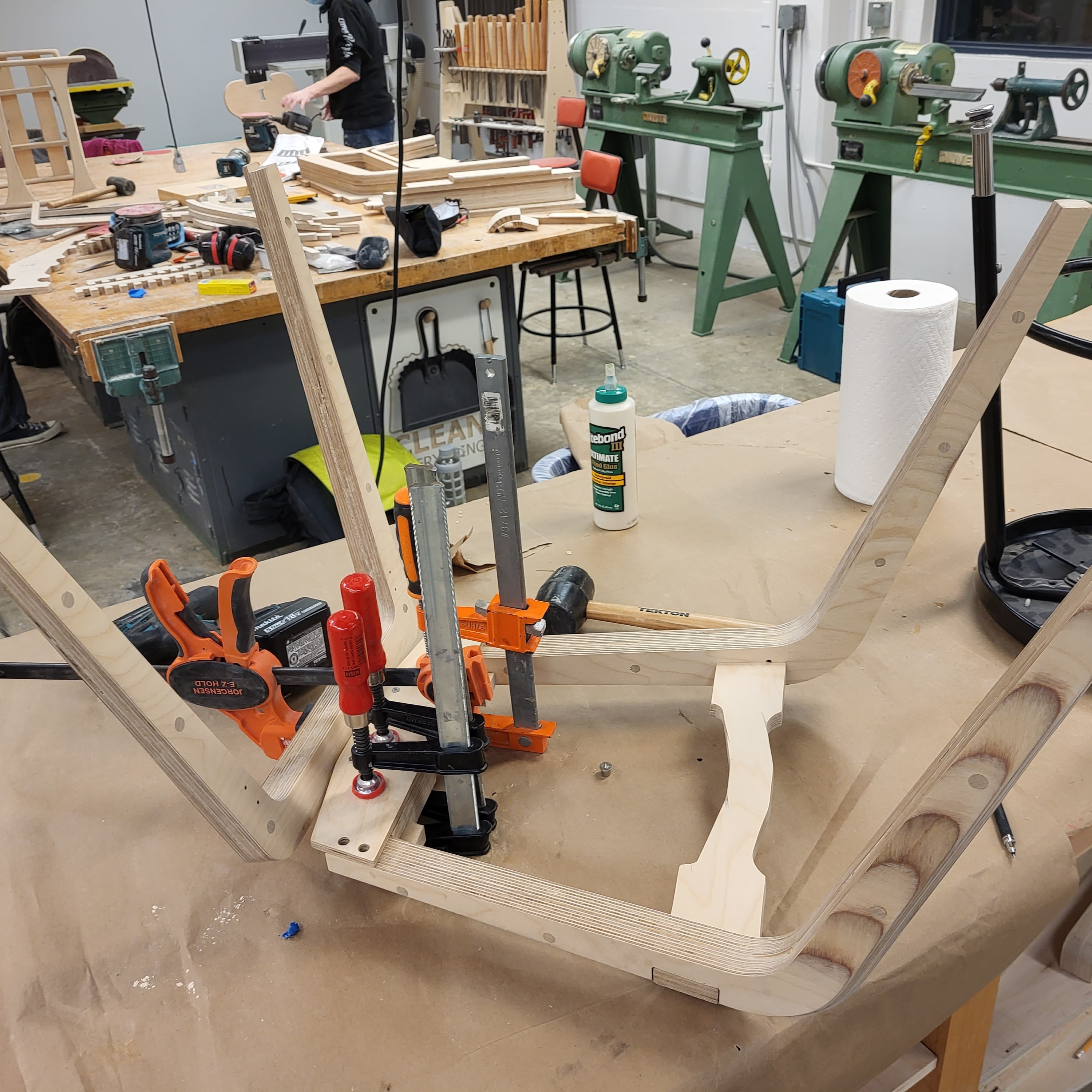
Then the front leg assembly and rear legs were glued into the subframe. The front leg attachment points were stabilized with dowels.
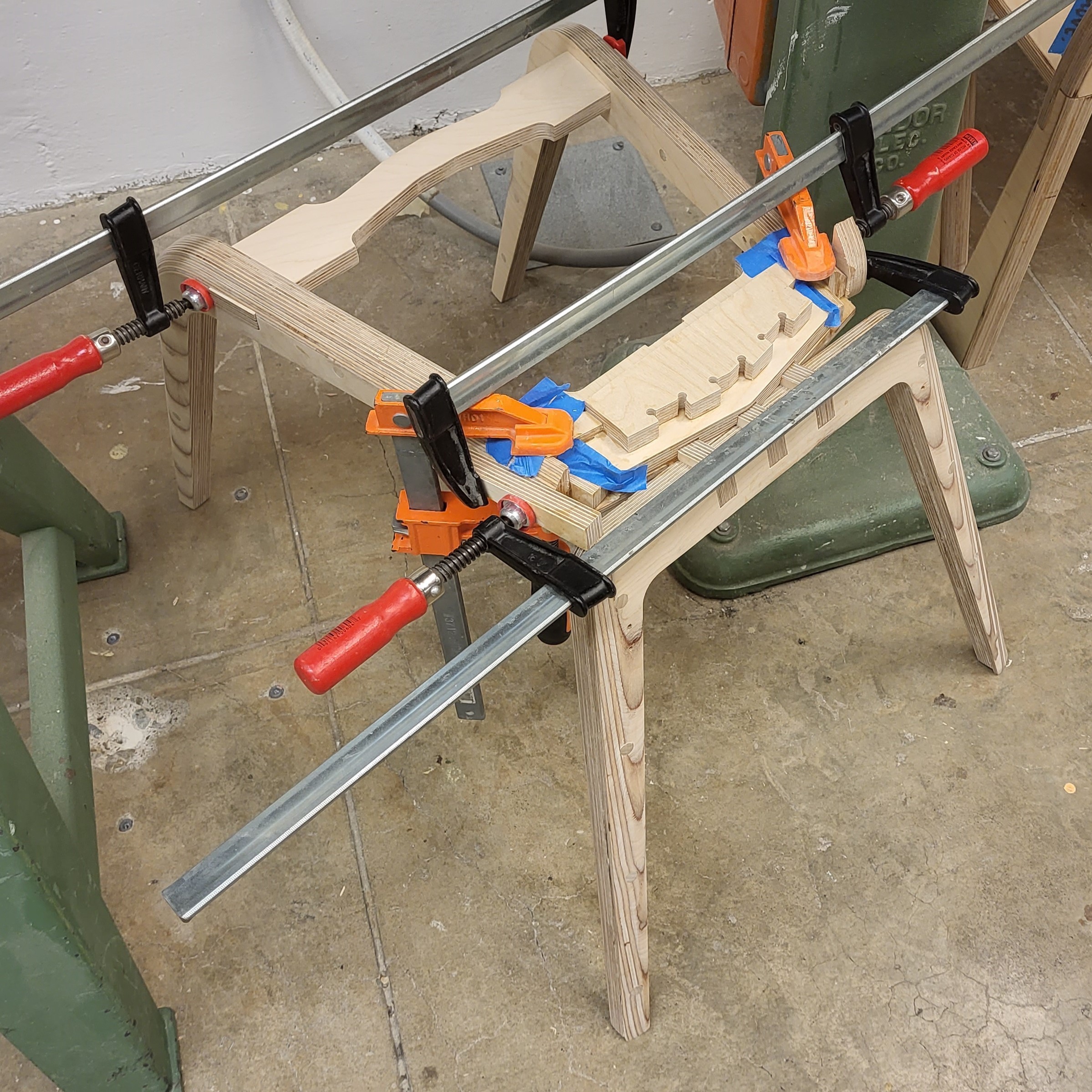
The chair is standing for the first time. Tape is used to prevent glue from leaking.
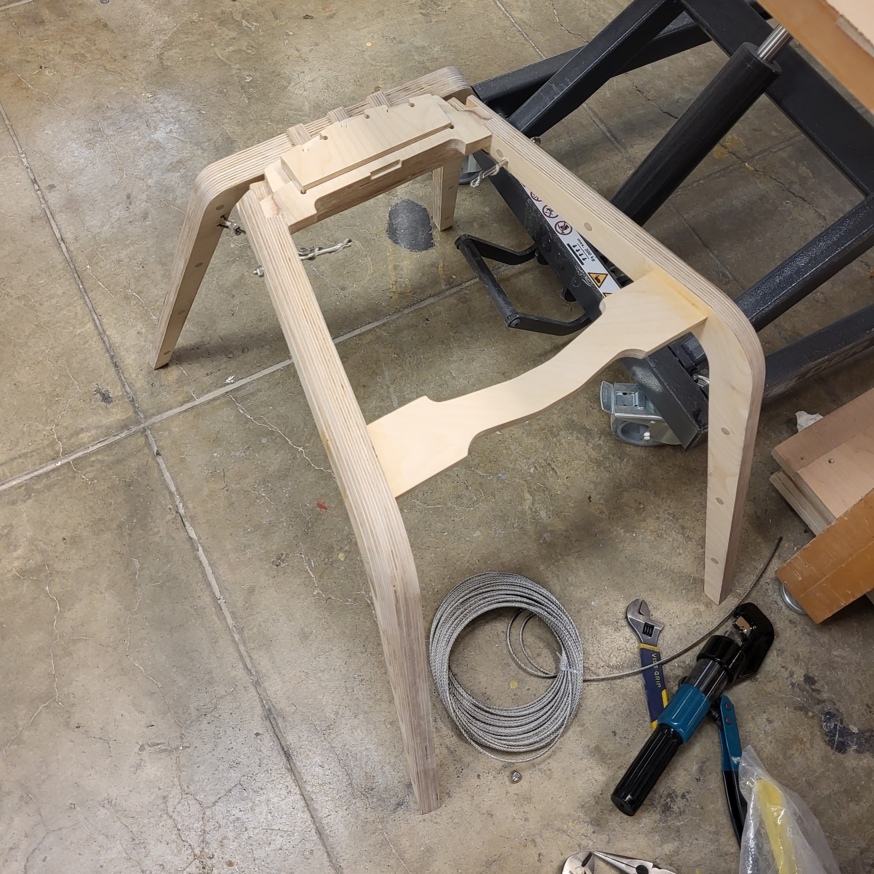
The cable and hardware is added to support the rear legs. The hardware was repurposed from a cable fence railing kit.
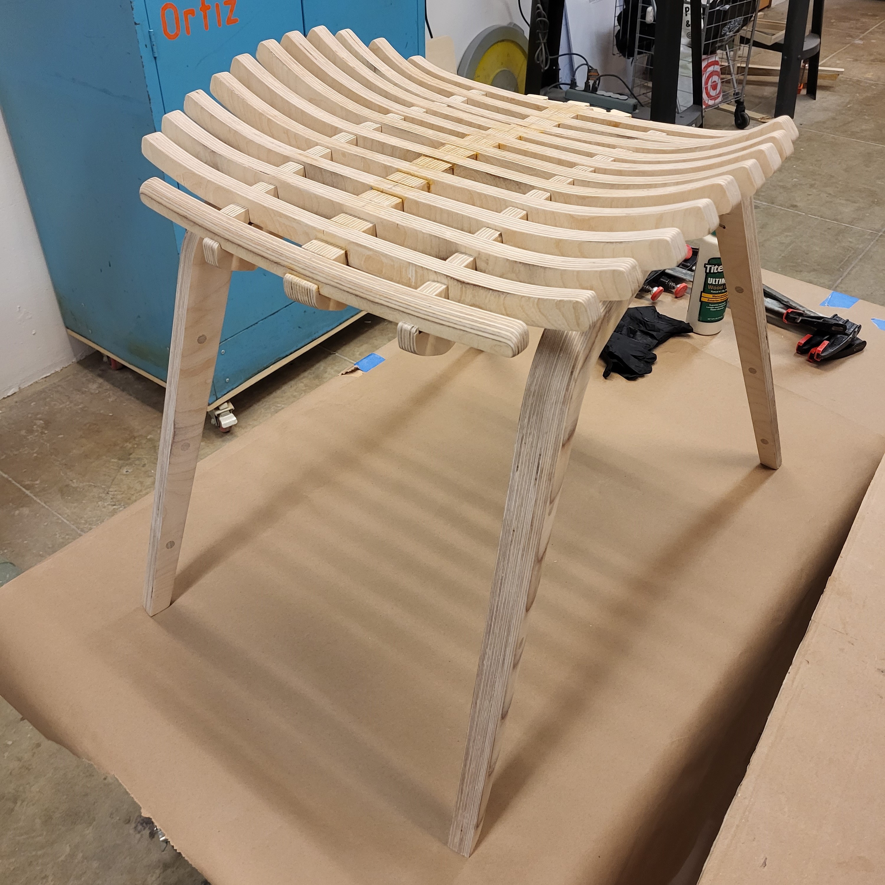
Seat supports and the seat assembly are glued at the same time.
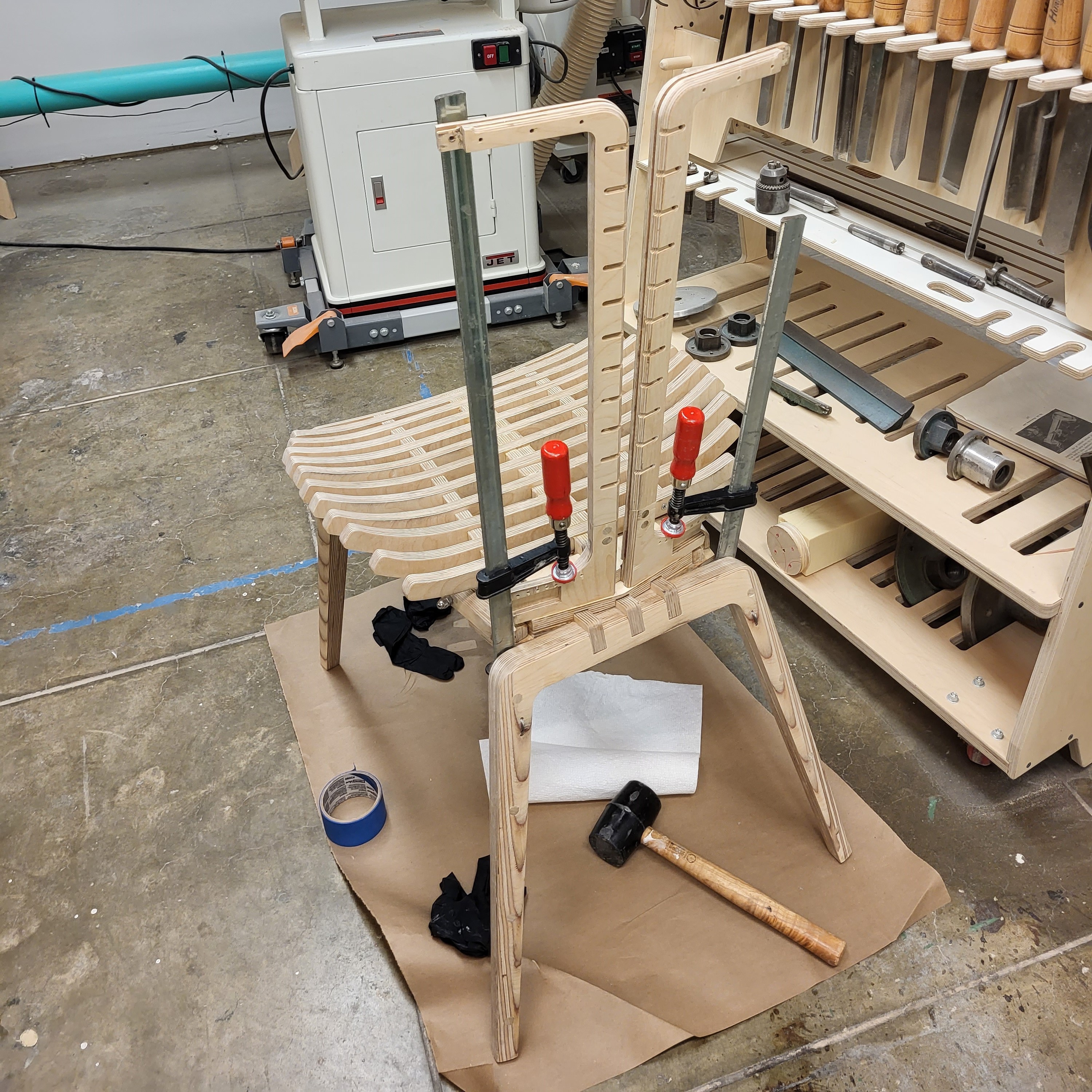
The inner backrest pieces are glued and clamped. They are tilted in three axis for ergonomics and style.
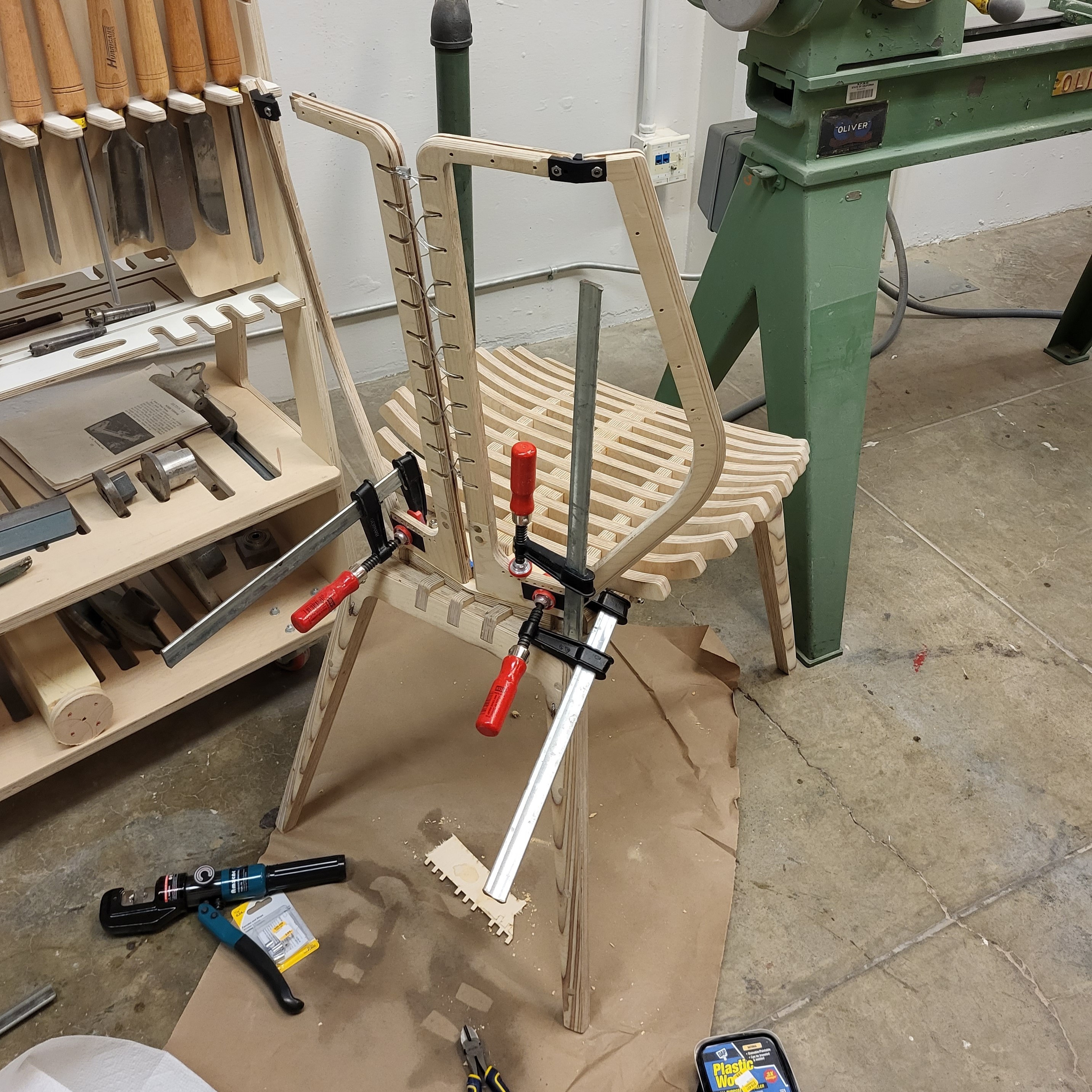
The outer backrest pieces and 3d printed joinery are then installed. The steel cable between the backrest pieces was replaced with cord.

CNC routing of my chair in progress, during a 3D contour operation.

After removal from the stock material, the edges were refined with a sanding sponge.

Several parts were designed with minor chisel work in mind. Visible "dogbones" were minimized.

The subframe was greatly complicated by the single-sided machining. All the pieces were glued and clamped across several steps.

The subframe part connects several parts at various complex angles.

The mill left a rough finish on part edges. Every part was finished to 400 grit in preparation for varnish. Pictured here is a seat slat.

The chair legs are made from two layers of plywood sheet and CNC contoured. I added dowels to stabilize the glued connection.

The excess dowels were sawed off and sanded flush, while the two layers were perfectly aligned with sanding.

To facilitate clamp placement, the slats had to be glued in multiple steps.

My slat-based design allowed me to create an erogonomic, supportive, organic seat shape. The goal was comfort without any upholstery.

Then the front leg assembly and rear legs were glued into the subframe. The front leg attachment points were stabilized with dowels.

Then the front leg assembly and rear legs were glued into the subframe. The front leg attachment points were stabilized with dowels.

The chair is standing for the first time. Tape is used to prevent glue from leaking.

The cable and hardware is added to support the rear legs. The hardware was repurposed from a cable fence railing kit.

Seat supports and the seat assembly are glued at the same time.

The inner backrest pieces are glued and clamped. They are tilted in three axis for ergonomics and style.

The outer backrest pieces and 3d printed joinery are then installed. The steel cable between the backrest pieces was replaced with cord.

CNC routing of my chair in progress, during a 3D contour operation.

After removal from the stock material, the edges were refined with a sanding sponge.

Several parts were designed with minor chisel work in mind. Visible "dogbones" were minimized.

The subframe was greatly complicated by the single-sided machining. All the pieces were glued and clamped across several steps.

The subframe part connects several parts at various complex angles.

The mill left a rough finish on part edges. Every part was finished to 400 grit in preparation for varnish. Pictured here is a seat slat.

The chair legs are made from two layers of plywood sheet and CNC contoured. I added dowels to stabilize the glued connection.

The excess dowels were sawed off and sanded flush, while the two layers were perfectly aligned with sanding.

To facilitate clamp placement, the slats had to be glued in multiple steps.

My slat-based design allowed me to create an erogonomic, supportive, organic seat shape. The goal was comfort without any upholstery.

Then the front leg assembly and rear legs were glued into the subframe. The front leg attachment points were stabilized with dowels.

Then the front leg assembly and rear legs were glued into the subframe. The front leg attachment points were stabilized with dowels.

The chair is standing for the first time. Tape is used to prevent glue from leaking.

The cable and hardware is added to support the rear legs. The hardware was repurposed from a cable fence railing kit.

Seat supports and the seat assembly are glued at the same time.

The inner backrest pieces are glued and clamped. They are tilted in three axis for ergonomics and style.

The outer backrest pieces and 3d printed joinery are then installed. The steel cable between the backrest pieces was replaced with cord.

CNC routing of my chair in progress, during a 3D contour operation.

After removal from the stock material, the edges were refined with a sanding sponge.

Several parts were designed with minor chisel work in mind. Visible "dogbones" were minimized.

The subframe was greatly complicated by the single-sided machining. All the pieces were glued and clamped across several steps.

The subframe part connects several parts at various complex angles.

The mill left a rough finish on part edges. Every part was finished to 400 grit in preparation for varnish. Pictured here is a seat slat.

The chair legs are made from two layers of plywood sheet and CNC contoured. I added dowels to stabilize the glued connection.

The excess dowels were sawed off and sanded flush, while the two layers were perfectly aligned with sanding.

To facilitate clamp placement, the slats had to be glued in multiple steps.

My slat-based design allowed me to create an erogonomic, supportive, organic seat shape. The goal was comfort without any upholstery.

Then the front leg assembly and rear legs were glued into the subframe. The front leg attachment points were stabilized with dowels.

Then the front leg assembly and rear legs were glued into the subframe. The front leg attachment points were stabilized with dowels.

The chair is standing for the first time. Tape is used to prevent glue from leaking.

The cable and hardware is added to support the rear legs. The hardware was repurposed from a cable fence railing kit.

Seat supports and the seat assembly are glued at the same time.

The inner backrest pieces are glued and clamped. They are tilted in three axis for ergonomics and style.

The outer backrest pieces and 3d printed joinery are then installed. The steel cable between the backrest pieces was replaced with cord.

CNC routing of my chair in progress, during a 3D contour operation.

After removal from the stock material, the edges were refined with a sanding sponge.

Several parts were designed with minor chisel work in mind. Visible "dogbones" were minimized.

The subframe was greatly complicated by the single-sided machining. All the pieces were glued and clamped across several steps.

The subframe part connects several parts at various complex angles.

The mill left a rough finish on part edges. Every part was finished to 400 grit in preparation for varnish. Pictured here is a seat slat.

The chair legs are made from two layers of plywood sheet and CNC contoured. I added dowels to stabilize the glued connection.

The excess dowels were sawed off and sanded flush, while the two layers were perfectly aligned with sanding.

To facilitate clamp placement, the slats had to be glued in multiple steps.

My slat-based design allowed me to create an erogonomic, supportive, organic seat shape. The goal was comfort without any upholstery.

Then the front leg assembly and rear legs were glued into the subframe. The front leg attachment points were stabilized with dowels.

Then the front leg assembly and rear legs were glued into the subframe. The front leg attachment points were stabilized with dowels.

The chair is standing for the first time. Tape is used to prevent glue from leaking.

The cable and hardware is added to support the rear legs. The hardware was repurposed from a cable fence railing kit.

Seat supports and the seat assembly are glued at the same time.

The inner backrest pieces are glued and clamped. They are tilted in three axis for ergonomics and style.

The outer backrest pieces and 3d printed joinery are then installed. The steel cable between the backrest pieces was replaced with cord.

CNC routing of my chair in progress, during a 3D contour operation.

After removal from the stock material, the edges were refined with a sanding sponge.

Several parts were designed with minor chisel work in mind. Visible "dogbones" were minimized.

The subframe was greatly complicated by the single-sided machining. All the pieces were glued and clamped across several steps.

The subframe part connects several parts at various complex angles.

The mill left a rough finish on part edges. Every part was finished to 400 grit in preparation for varnish. Pictured here is a seat slat.

The chair legs are made from two layers of plywood sheet and CNC contoured. I added dowels to stabilize the glued connection.

The excess dowels were sawed off and sanded flush, while the two layers were perfectly aligned with sanding.

To facilitate clamp placement, the slats had to be glued in multiple steps.

My slat-based design allowed me to create an erogonomic, supportive, organic seat shape. The goal was comfort without any upholstery.

Then the front leg assembly and rear legs were glued into the subframe. The front leg attachment points were stabilized with dowels.

Then the front leg assembly and rear legs were glued into the subframe. The front leg attachment points were stabilized with dowels.

The chair is standing for the first time. Tape is used to prevent glue from leaking.

The cable and hardware is added to support the rear legs. The hardware was repurposed from a cable fence railing kit.

Seat supports and the seat assembly are glued at the same time.

The inner backrest pieces are glued and clamped. They are tilted in three axis for ergonomics and style.

The outer backrest pieces and 3d printed joinery are then installed. The steel cable between the backrest pieces was replaced with cord.

CNC routing of my chair in progress, during a 3D contour operation.

After removal from the stock material, the edges were refined with a sanding sponge.

Several parts were designed with minor chisel work in mind. Visible "dogbones" were minimized.

The subframe was greatly complicated by the single-sided machining. All the pieces were glued and clamped across several steps.

The subframe part connects several parts at various complex angles.

The mill left a rough finish on part edges. Every part was finished to 400 grit in preparation for varnish. Pictured here is a seat slat.

The chair legs are made from two layers of plywood sheet and CNC contoured. I added dowels to stabilize the glued connection.

The excess dowels were sawed off and sanded flush, while the two layers were perfectly aligned with sanding.

To facilitate clamp placement, the slats had to be glued in multiple steps.

My slat-based design allowed me to create an erogonomic, supportive, organic seat shape. The goal was comfort without any upholstery.

Then the front leg assembly and rear legs were glued into the subframe. The front leg attachment points were stabilized with dowels.

Then the front leg assembly and rear legs were glued into the subframe. The front leg attachment points were stabilized with dowels.

The chair is standing for the first time. Tape is used to prevent glue from leaking.

The cable and hardware is added to support the rear legs. The hardware was repurposed from a cable fence railing kit.

Seat supports and the seat assembly are glued at the same time.

The inner backrest pieces are glued and clamped. They are tilted in three axis for ergonomics and style.

The outer backrest pieces and 3d printed joinery are then installed. The steel cable between the backrest pieces was replaced with cord.

CNC routing of my chair in progress, during a 3D contour operation.

After removal from the stock material, the edges were refined with a sanding sponge.

Several parts were designed with minor chisel work in mind. Visible "dogbones" were minimized.

The subframe was greatly complicated by the single-sided machining. All the pieces were glued and clamped across several steps.

The subframe part connects several parts at various complex angles.

The mill left a rough finish on part edges. Every part was finished to 400 grit in preparation for varnish. Pictured here is a seat slat.

The chair legs are made from two layers of plywood sheet and CNC contoured. I added dowels to stabilize the glued connection.

The excess dowels were sawed off and sanded flush, while the two layers were perfectly aligned with sanding.

To facilitate clamp placement, the slats had to be glued in multiple steps.

My slat-based design allowed me to create an erogonomic, supportive, organic seat shape. The goal was comfort without any upholstery.

Then the front leg assembly and rear legs were glued into the subframe. The front leg attachment points were stabilized with dowels.

Then the front leg assembly and rear legs were glued into the subframe. The front leg attachment points were stabilized with dowels.

The chair is standing for the first time. Tape is used to prevent glue from leaking.

The cable and hardware is added to support the rear legs. The hardware was repurposed from a cable fence railing kit.

Seat supports and the seat assembly are glued at the same time.

The inner backrest pieces are glued and clamped. They are tilted in three axis for ergonomics and style.

The outer backrest pieces and 3d printed joinery are then installed. The steel cable between the backrest pieces was replaced with cord.

CNC routing of my chair in progress, during a 3D contour operation.

After removal from the stock material, the edges were refined with a sanding sponge.

Several parts were designed with minor chisel work in mind. Visible "dogbones" were minimized.

The subframe was greatly complicated by the single-sided machining. All the pieces were glued and clamped across several steps.

The subframe part connects several parts at various complex angles.

The mill left a rough finish on part edges. Every part was finished to 400 grit in preparation for varnish. Pictured here is a seat slat.

The chair legs are made from two layers of plywood sheet and CNC contoured. I added dowels to stabilize the glued connection.

The excess dowels were sawed off and sanded flush, while the two layers were perfectly aligned with sanding.

To facilitate clamp placement, the slats had to be glued in multiple steps.

My slat-based design allowed me to create an erogonomic, supportive, organic seat shape. The goal was comfort without any upholstery.

Then the front leg assembly and rear legs were glued into the subframe. The front leg attachment points were stabilized with dowels.

Then the front leg assembly and rear legs were glued into the subframe. The front leg attachment points were stabilized with dowels.

The chair is standing for the first time. Tape is used to prevent glue from leaking.

The cable and hardware is added to support the rear legs. The hardware was repurposed from a cable fence railing kit.

Seat supports and the seat assembly are glued at the same time.

The inner backrest pieces are glued and clamped. They are tilted in three axis for ergonomics and style.

The outer backrest pieces and 3d printed joinery are then installed. The steel cable between the backrest pieces was replaced with cord.

CNC routing of my chair in progress, during a 3D contour operation.

After removal from the stock material, the edges were refined with a sanding sponge.

Several parts were designed with minor chisel work in mind. Visible "dogbones" were minimized.

The subframe was greatly complicated by the single-sided machining. All the pieces were glued and clamped across several steps.

The subframe part connects several parts at various complex angles.

The mill left a rough finish on part edges. Every part was finished to 400 grit in preparation for varnish. Pictured here is a seat slat.

The chair legs are made from two layers of plywood sheet and CNC contoured. I added dowels to stabilize the glued connection.

The excess dowels were sawed off and sanded flush, while the two layers were perfectly aligned with sanding.

To facilitate clamp placement, the slats had to be glued in multiple steps.

My slat-based design allowed me to create an erogonomic, supportive, organic seat shape. The goal was comfort without any upholstery.

Then the front leg assembly and rear legs were glued into the subframe. The front leg attachment points were stabilized with dowels.

Then the front leg assembly and rear legs were glued into the subframe. The front leg attachment points were stabilized with dowels.

The chair is standing for the first time. Tape is used to prevent glue from leaking.

The cable and hardware is added to support the rear legs. The hardware was repurposed from a cable fence railing kit.

Seat supports and the seat assembly are glued at the same time.

The inner backrest pieces are glued and clamped. They are tilted in three axis for ergonomics and style.

The outer backrest pieces and 3d printed joinery are then installed. The steel cable between the backrest pieces was replaced with cord.

CNC routing of my chair in progress, during a 3D contour operation.

After removal from the stock material, the edges were refined with a sanding sponge.

Several parts were designed with minor chisel work in mind. Visible "dogbones" were minimized.

The subframe was greatly complicated by the single-sided machining. All the pieces were glued and clamped across several steps.

The subframe part connects several parts at various complex angles.

The mill left a rough finish on part edges. Every part was finished to 400 grit in preparation for varnish. Pictured here is a seat slat.

The chair legs are made from two layers of plywood sheet and CNC contoured. I added dowels to stabilize the glued connection.

The excess dowels were sawed off and sanded flush, while the two layers were perfectly aligned with sanding.

To facilitate clamp placement, the slats had to be glued in multiple steps.

My slat-based design allowed me to create an erogonomic, supportive, organic seat shape. The goal was comfort without any upholstery.

Then the front leg assembly and rear legs were glued into the subframe. The front leg attachment points were stabilized with dowels.

Then the front leg assembly and rear legs were glued into the subframe. The front leg attachment points were stabilized with dowels.

The chair is standing for the first time. Tape is used to prevent glue from leaking.

The cable and hardware is added to support the rear legs. The hardware was repurposed from a cable fence railing kit.

Seat supports and the seat assembly are glued at the same time.

The inner backrest pieces are glued and clamped. They are tilted in three axis for ergonomics and style.

The outer backrest pieces and 3d printed joinery are then installed. The steel cable between the backrest pieces was replaced with cord.

CNC routing of my chair in progress, during a 3D contour operation.

After removal from the stock material, the edges were refined with a sanding sponge.

Several parts were designed with minor chisel work in mind. Visible "dogbones" were minimized.

The subframe was greatly complicated by the single-sided machining. All the pieces were glued and clamped across several steps.

The subframe part connects several parts at various complex angles.

The mill left a rough finish on part edges. Every part was finished to 400 grit in preparation for varnish. Pictured here is a seat slat.

The chair legs are made from two layers of plywood sheet and CNC contoured. I added dowels to stabilize the glued connection.

The excess dowels were sawed off and sanded flush, while the two layers were perfectly aligned with sanding.

To facilitate clamp placement, the slats had to be glued in multiple steps.

My slat-based design allowed me to create an erogonomic, supportive, organic seat shape. The goal was comfort without any upholstery.

Then the front leg assembly and rear legs were glued into the subframe. The front leg attachment points were stabilized with dowels.

Then the front leg assembly and rear legs were glued into the subframe. The front leg attachment points were stabilized with dowels.

The chair is standing for the first time. Tape is used to prevent glue from leaking.

The cable and hardware is added to support the rear legs. The hardware was repurposed from a cable fence railing kit.

Seat supports and the seat assembly are glued at the same time.

The inner backrest pieces are glued and clamped. They are tilted in three axis for ergonomics and style.

The outer backrest pieces and 3d printed joinery are then installed. The steel cable between the backrest pieces was replaced with cord.
Fabrication Process

CNC routing of my chair in progress, during a 3D contour operation.

After removal from the stock material, the edges were refined with a sanding sponge.

Several parts were designed with minor chisel work in mind. Visible "dogbones" were minimized.

The subframe was greatly complicated by the single-sided machining. All the pieces were glued and clamped across several steps.

The subframe part connects several parts at various complex angles.

The mill left a rough finish on part edges. Every part was finished to 400 grit in preparation for varnish. Pictured here is a seat slat.

The chair legs are made from two layers of plywood sheet and CNC contoured. I added dowels to stabilize the glued connection.

The excess dowels were sawed off and sanded flush, while the two layers were perfectly aligned with sanding.

To facilitate clamp placement, the slats had to be glued in multiple steps.

My slat-based design allowed me to create an erogonomic, supportive, organic seat shape. The goal was comfort without any upholstery.

Then the front leg assembly and rear legs were glued into the subframe. The front leg attachment points were stabilized with dowels.

Then the front leg assembly and rear legs were glued into the subframe. The front leg attachment points were stabilized with dowels.

The chair is standing for the first time. Tape is used to prevent glue from leaking.

The cable and hardware is added to support the rear legs. The hardware was repurposed from a cable fence railing kit.

Seat supports and the seat assembly are glued at the same time.

The inner backrest pieces are glued and clamped. They are tilted in three axis for ergonomics and style.

The outer backrest pieces and 3d printed joinery are then installed. The steel cable between the backrest pieces was replaced with cord.

CNC routing of my chair in progress, during a 3D contour operation.

After removal from the stock material, the edges were refined with a sanding sponge.

Several parts were designed with minor chisel work in mind. Visible "dogbones" were minimized.

The subframe was greatly complicated by the single-sided machining. All the pieces were glued and clamped across several steps.

The subframe part connects several parts at various complex angles.

The mill left a rough finish on part edges. Every part was finished to 400 grit in preparation for varnish. Pictured here is a seat slat.

The chair legs are made from two layers of plywood sheet and CNC contoured. I added dowels to stabilize the glued connection.

The excess dowels were sawed off and sanded flush, while the two layers were perfectly aligned with sanding.

To facilitate clamp placement, the slats had to be glued in multiple steps.

My slat-based design allowed me to create an erogonomic, supportive, organic seat shape. The goal was comfort without any upholstery.

Then the front leg assembly and rear legs were glued into the subframe. The front leg attachment points were stabilized with dowels.

Then the front leg assembly and rear legs were glued into the subframe. The front leg attachment points were stabilized with dowels.

The chair is standing for the first time. Tape is used to prevent glue from leaking.

The cable and hardware is added to support the rear legs. The hardware was repurposed from a cable fence railing kit.

Seat supports and the seat assembly are glued at the same time.

The inner backrest pieces are glued and clamped. They are tilted in three axis for ergonomics and style.

The outer backrest pieces and 3d printed joinery are then installed. The steel cable between the backrest pieces was replaced with cord.

CNC routing of my chair in progress, during a 3D contour operation.

After removal from the stock material, the edges were refined with a sanding sponge.

Several parts were designed with minor chisel work in mind. Visible "dogbones" were minimized.

The subframe was greatly complicated by the single-sided machining. All the pieces were glued and clamped across several steps.

The subframe part connects several parts at various complex angles.

The mill left a rough finish on part edges. Every part was finished to 400 grit in preparation for varnish. Pictured here is a seat slat.

The chair legs are made from two layers of plywood sheet and CNC contoured. I added dowels to stabilize the glued connection.

The excess dowels were sawed off and sanded flush, while the two layers were perfectly aligned with sanding.

To facilitate clamp placement, the slats had to be glued in multiple steps.

My slat-based design allowed me to create an erogonomic, supportive, organic seat shape. The goal was comfort without any upholstery.

Then the front leg assembly and rear legs were glued into the subframe. The front leg attachment points were stabilized with dowels.

Then the front leg assembly and rear legs were glued into the subframe. The front leg attachment points were stabilized with dowels.

The chair is standing for the first time. Tape is used to prevent glue from leaking.

The cable and hardware is added to support the rear legs. The hardware was repurposed from a cable fence railing kit.

Seat supports and the seat assembly are glued at the same time.

The inner backrest pieces are glued and clamped. They are tilted in three axis for ergonomics and style.

The outer backrest pieces and 3d printed joinery are then installed. The steel cable between the backrest pieces was replaced with cord.

CNC routing of my chair in progress, during a 3D contour operation.

After removal from the stock material, the edges were refined with a sanding sponge.

Several parts were designed with minor chisel work in mind. Visible "dogbones" were minimized.

The subframe was greatly complicated by the single-sided machining. All the pieces were glued and clamped across several steps.

The subframe part connects several parts at various complex angles.

The mill left a rough finish on part edges. Every part was finished to 400 grit in preparation for varnish. Pictured here is a seat slat.

The chair legs are made from two layers of plywood sheet and CNC contoured. I added dowels to stabilize the glued connection.

The excess dowels were sawed off and sanded flush, while the two layers were perfectly aligned with sanding.

To facilitate clamp placement, the slats had to be glued in multiple steps.

My slat-based design allowed me to create an erogonomic, supportive, organic seat shape. The goal was comfort without any upholstery.

Then the front leg assembly and rear legs were glued into the subframe. The front leg attachment points were stabilized with dowels.

Then the front leg assembly and rear legs were glued into the subframe. The front leg attachment points were stabilized with dowels.

The chair is standing for the first time. Tape is used to prevent glue from leaking.

The cable and hardware is added to support the rear legs. The hardware was repurposed from a cable fence railing kit.

Seat supports and the seat assembly are glued at the same time.

The inner backrest pieces are glued and clamped. They are tilted in three axis for ergonomics and style.

The outer backrest pieces and 3d printed joinery are then installed. The steel cable between the backrest pieces was replaced with cord.
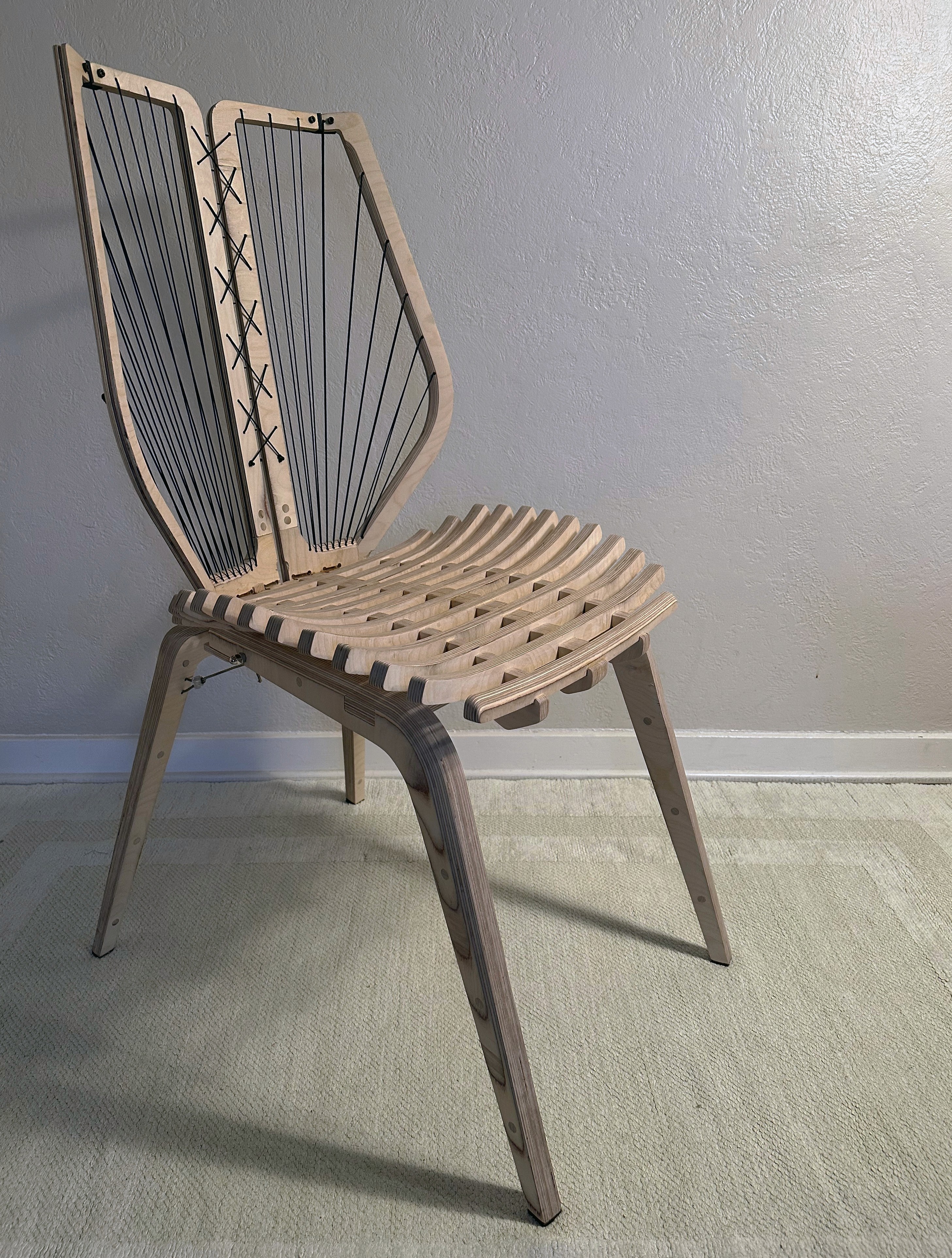
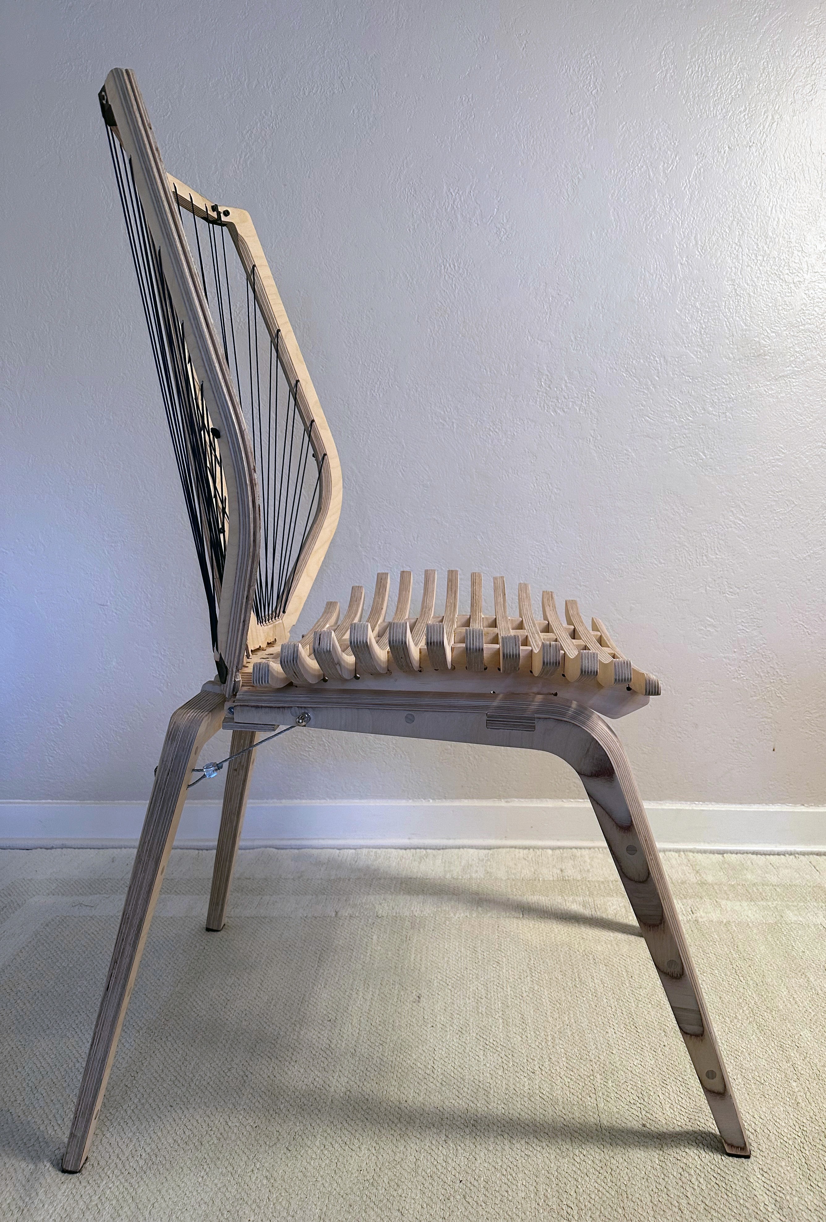
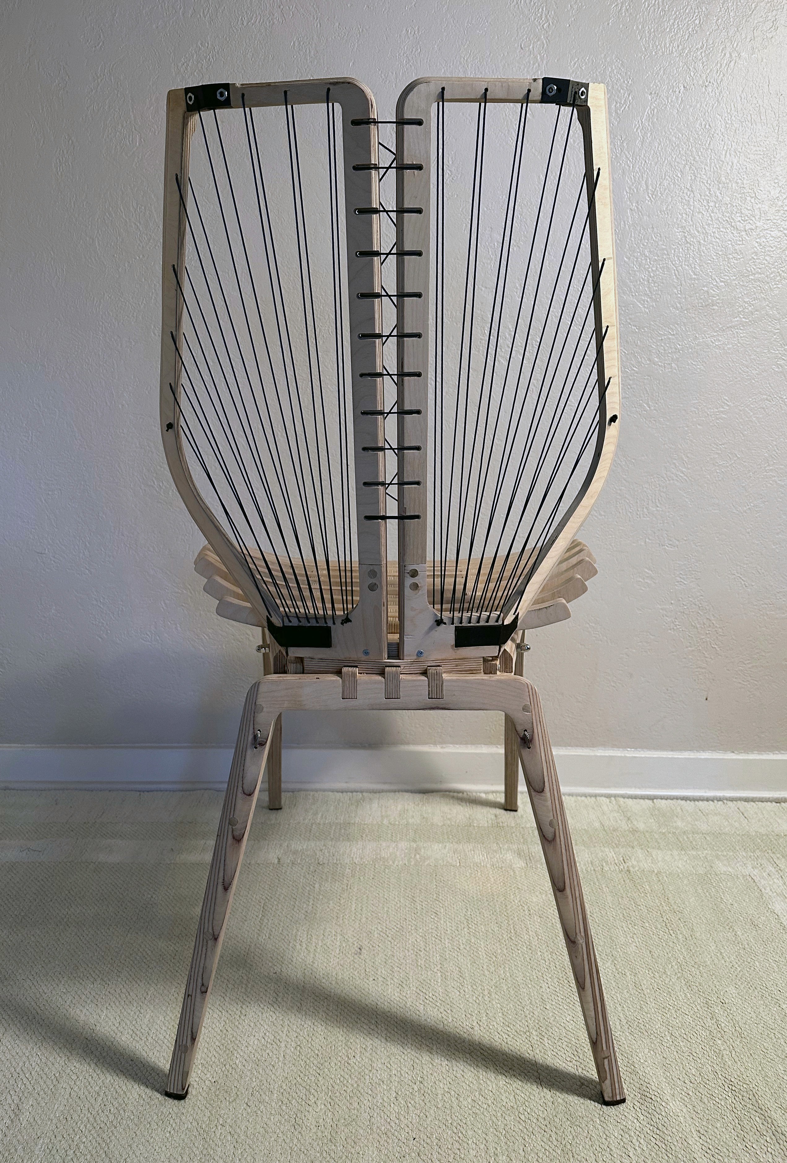
After the cord was added, the chair was varnished and finished one last time. The resulting chair was exceptionally comfortable considering the lack of upholstery. The base was extremely stable with no wobble and conformed well to human anatomy. The backrest was designed to offer adaptive back support and could hold my weight. Although I hadn't tested its limits, I still wanted to strengthen and rework the backrest in a future iteration.
Images of the finished "version one" compound chair.
Version Two
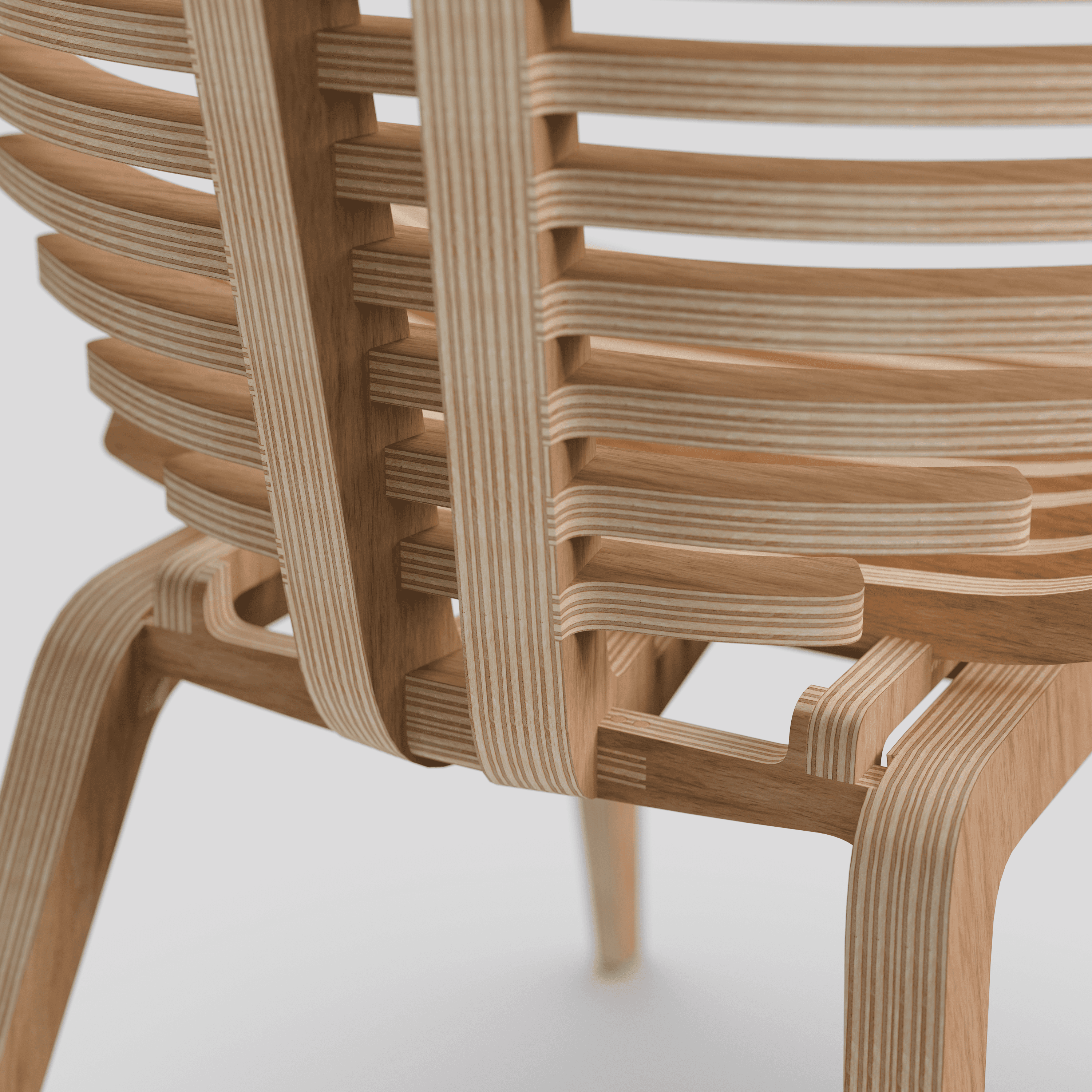
Throughout the process of designing, building, and testing version one, I learned a great deal about furniture construction and design. With this knowledge, I set out to create a second version.
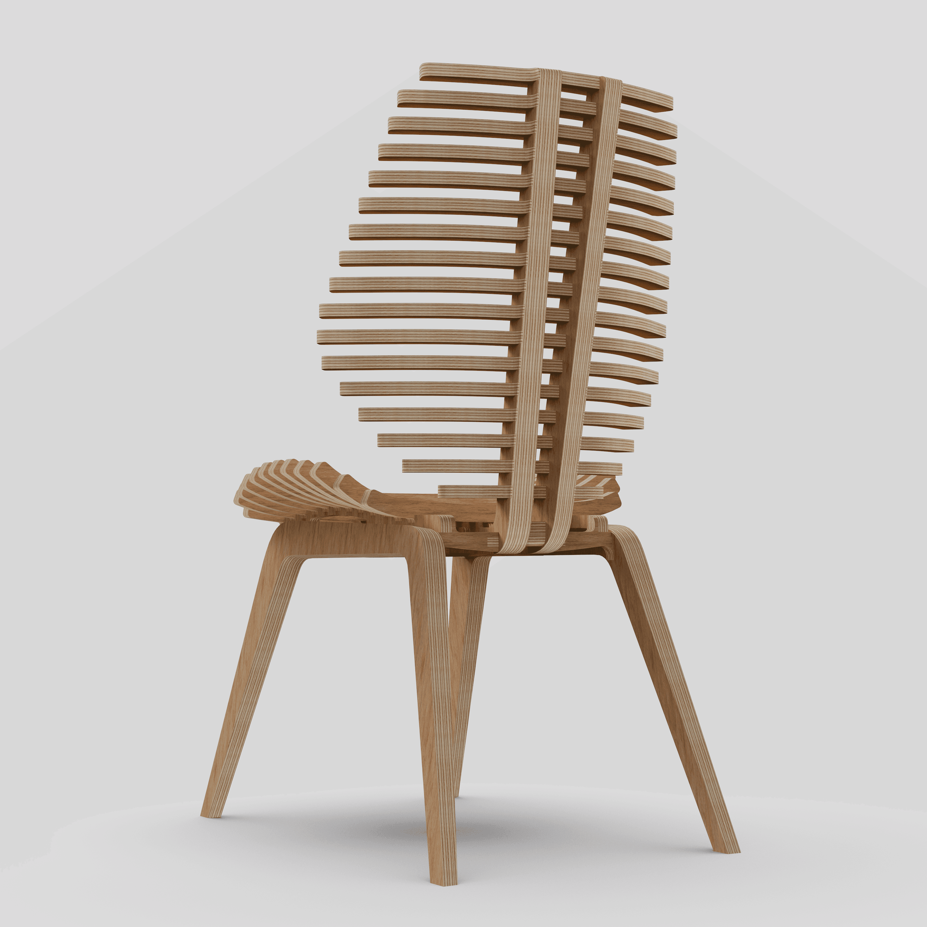
One of the most common pieces of feedback I received on the first version was that the design featured too many disparate design elements. I agreed that the design felt somewhat disjointed or eclectic in places. Therefore, my primary focus for version two was to incorporate the design together, making every part feel like it belongs.
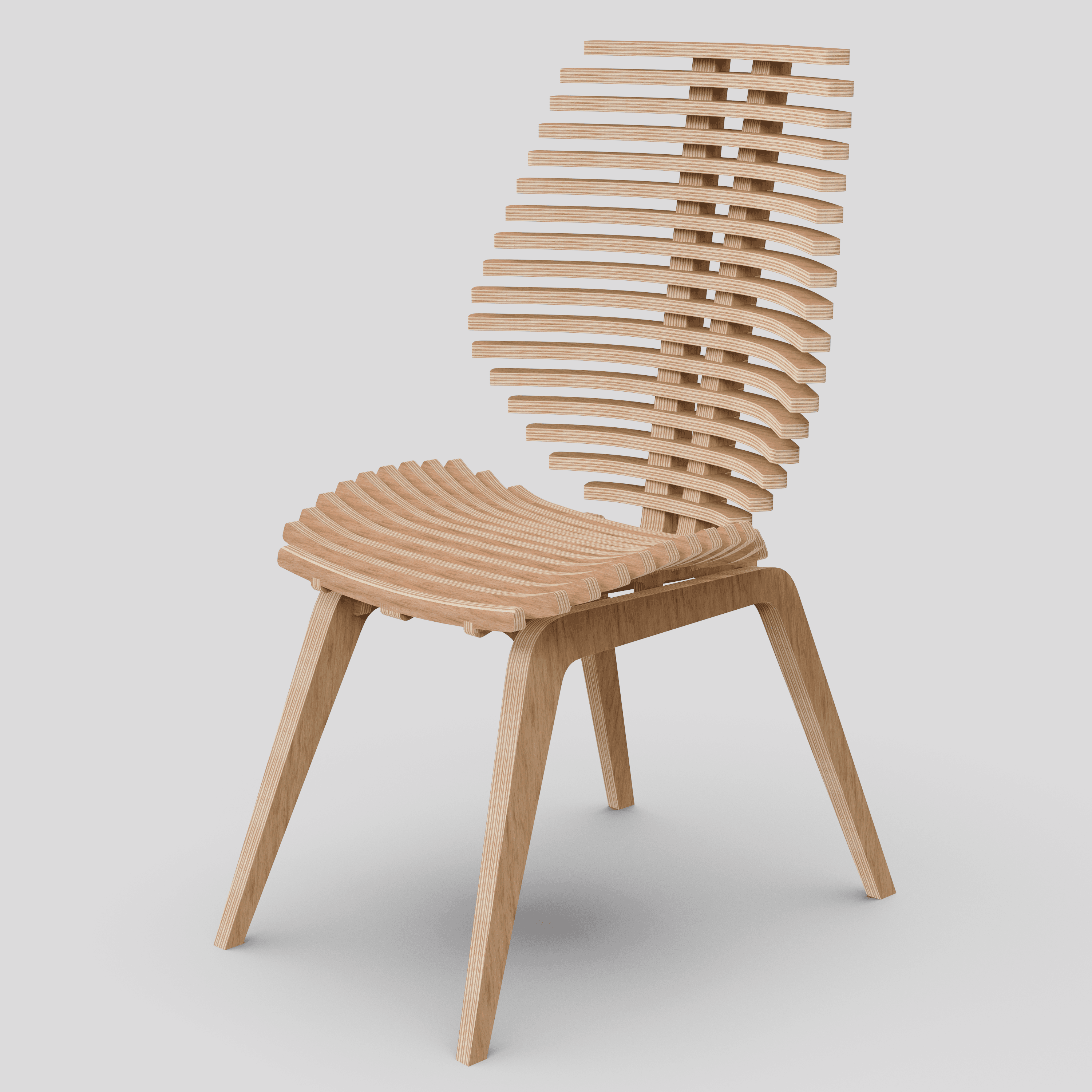

Version two is a complete redesign, with every single part being heavily revised. The cord and cable were ditched this time around. I believe those ideas have potential, but I think it's important to apply them to the right project. Likewise, there are no more 3D printed joinery or bolts.
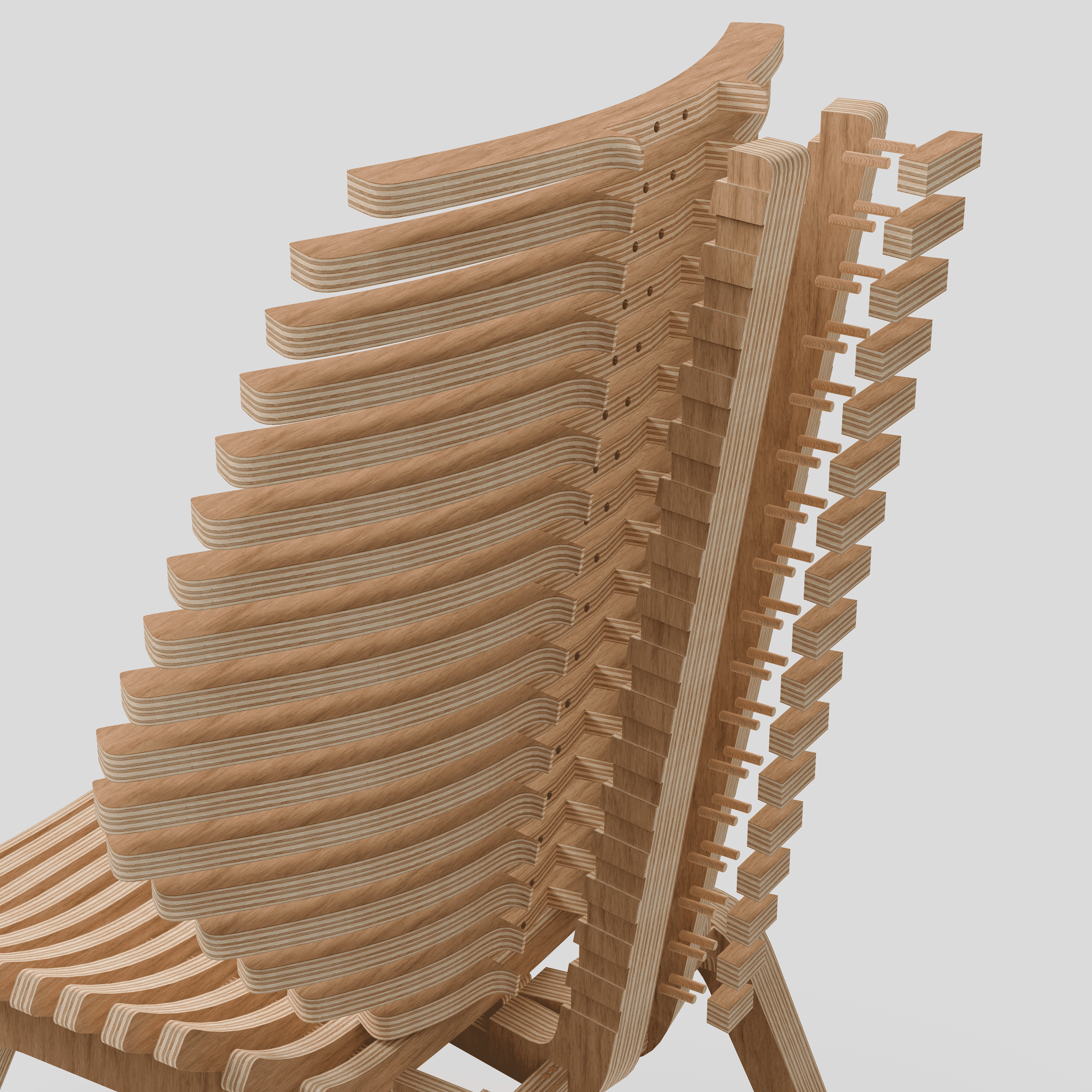
The new back imitates the original seat structure while retaining the same contouring and silhouette of the previous version. It should also be much stronger than before.
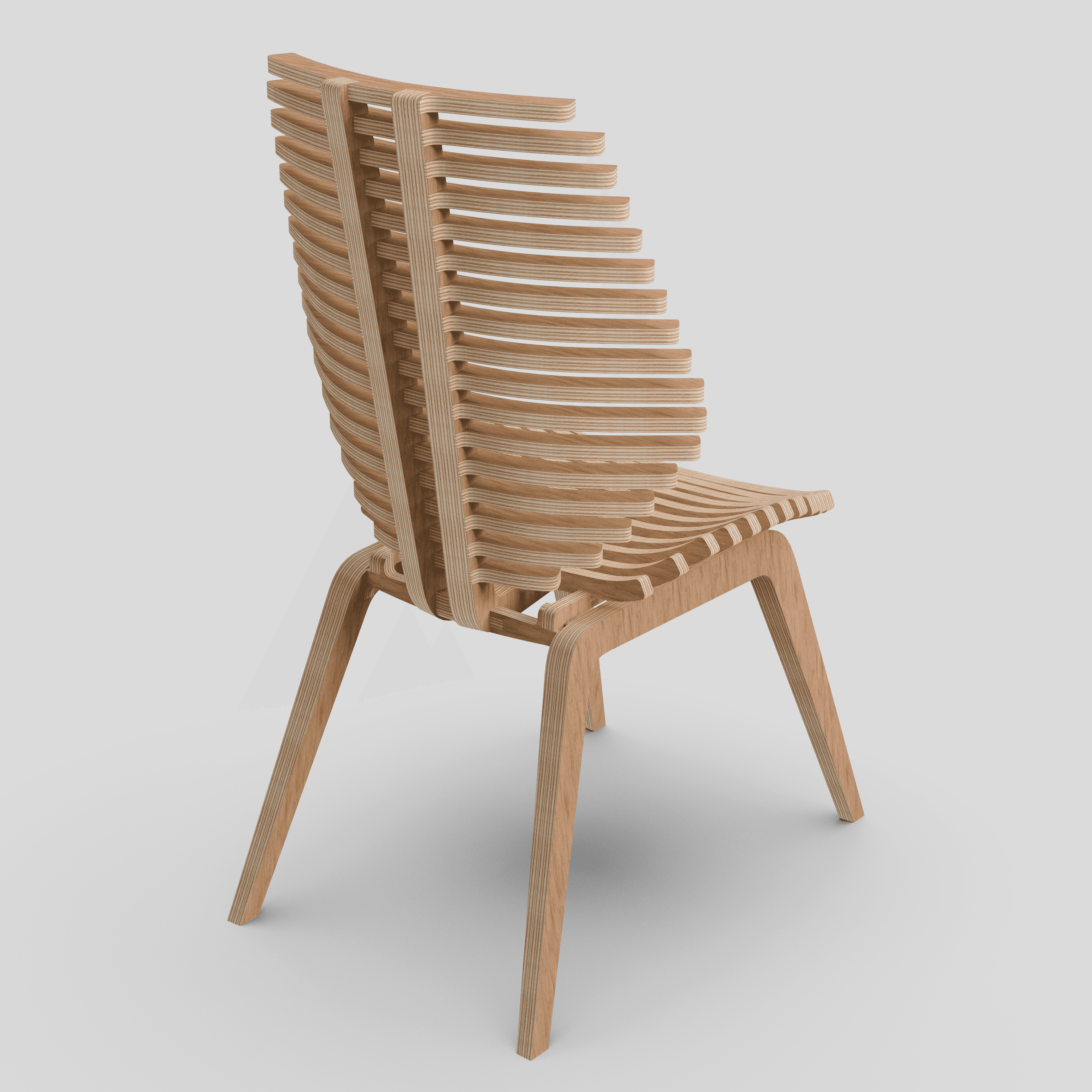

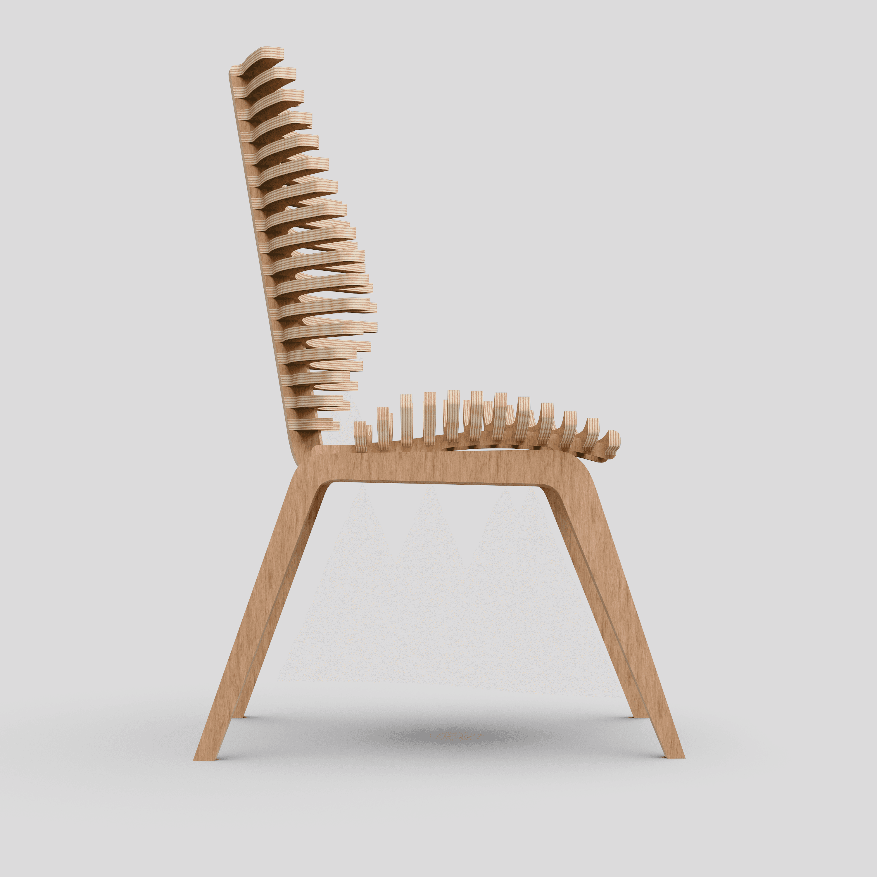

The new legs have a better flow, no longer being visibly disjointed.
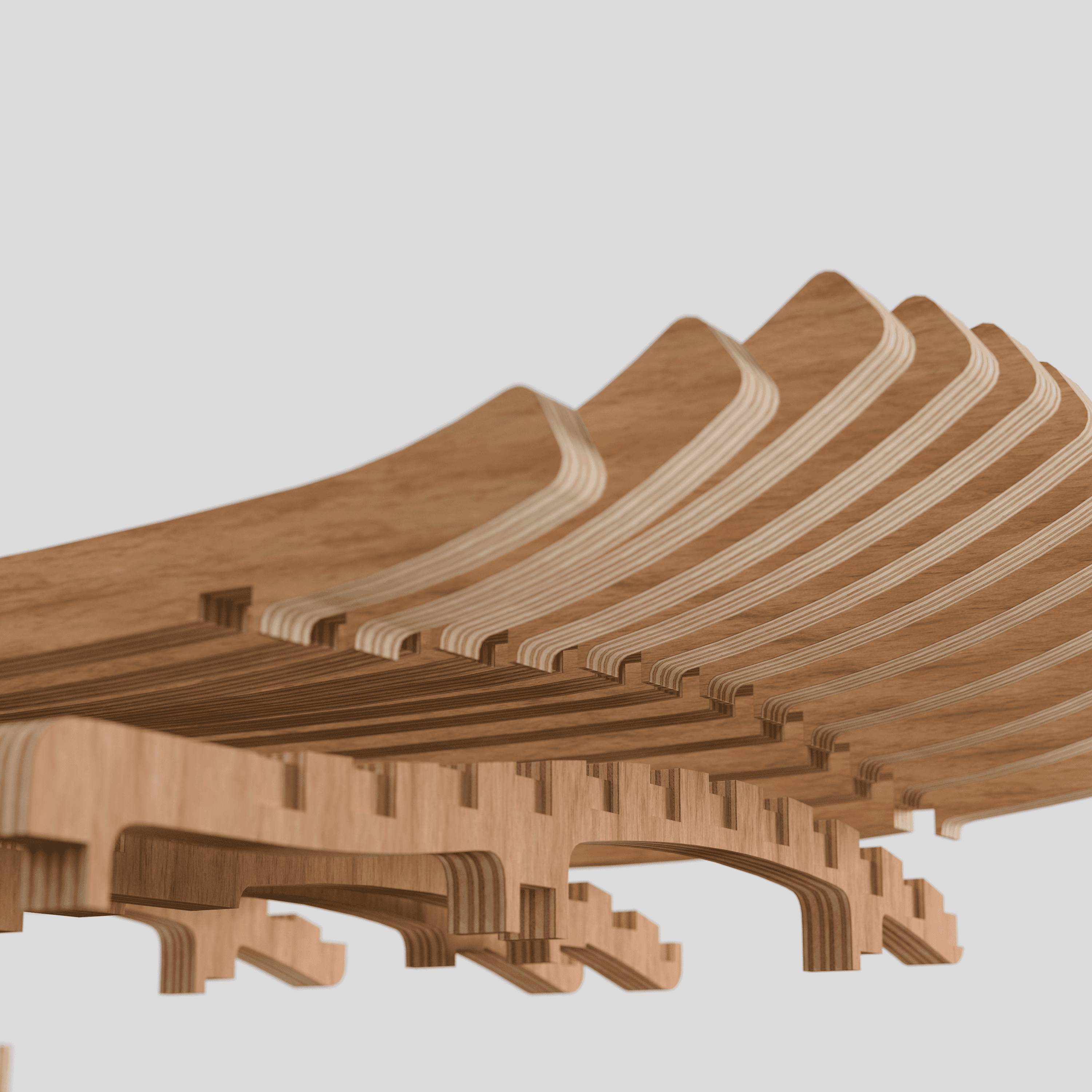
The complicated subframe assembly has been replaced with the new back and a series of three cross braces that span the width of the chair.


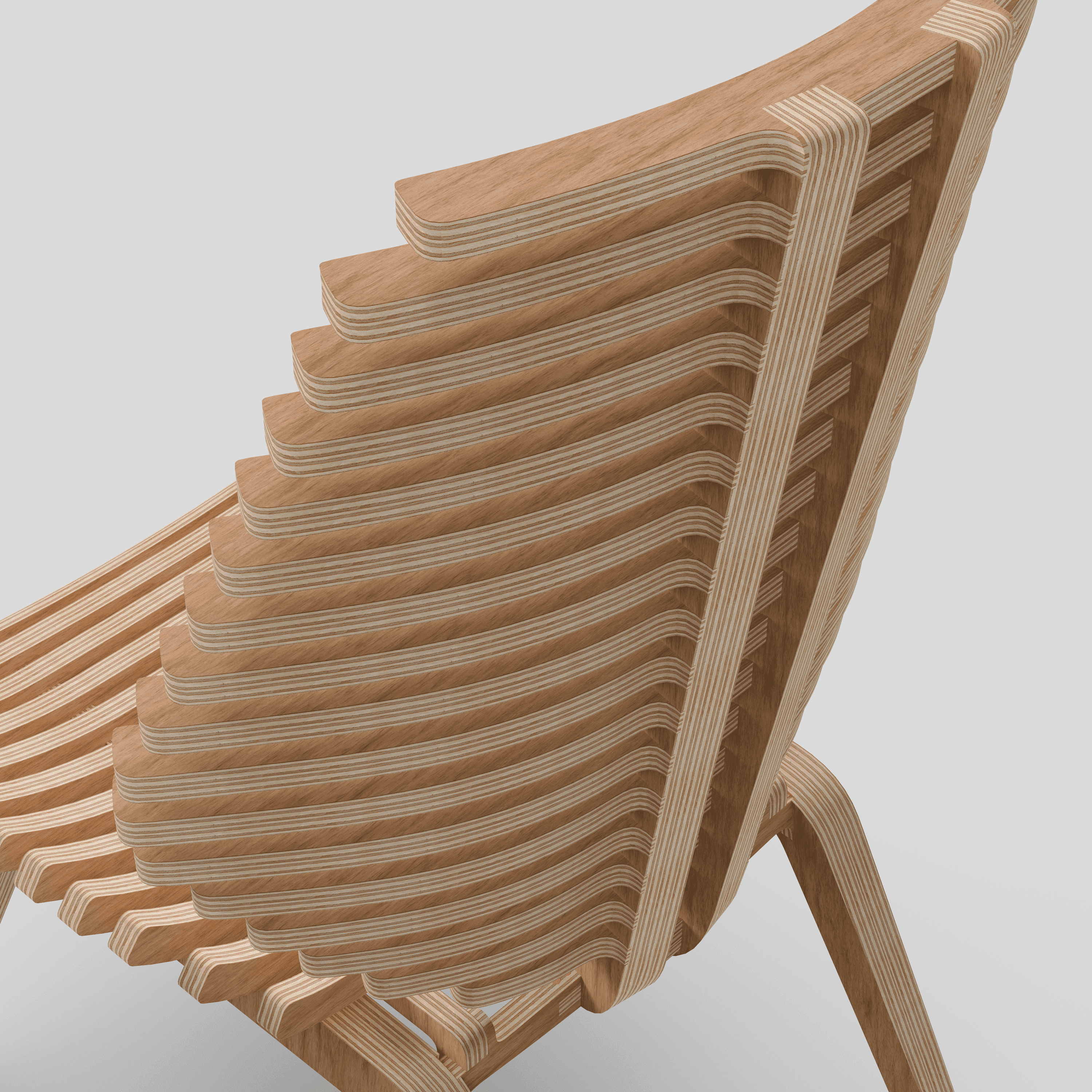

Parts are incorporated and blended together for a refined and unified aesthetic.
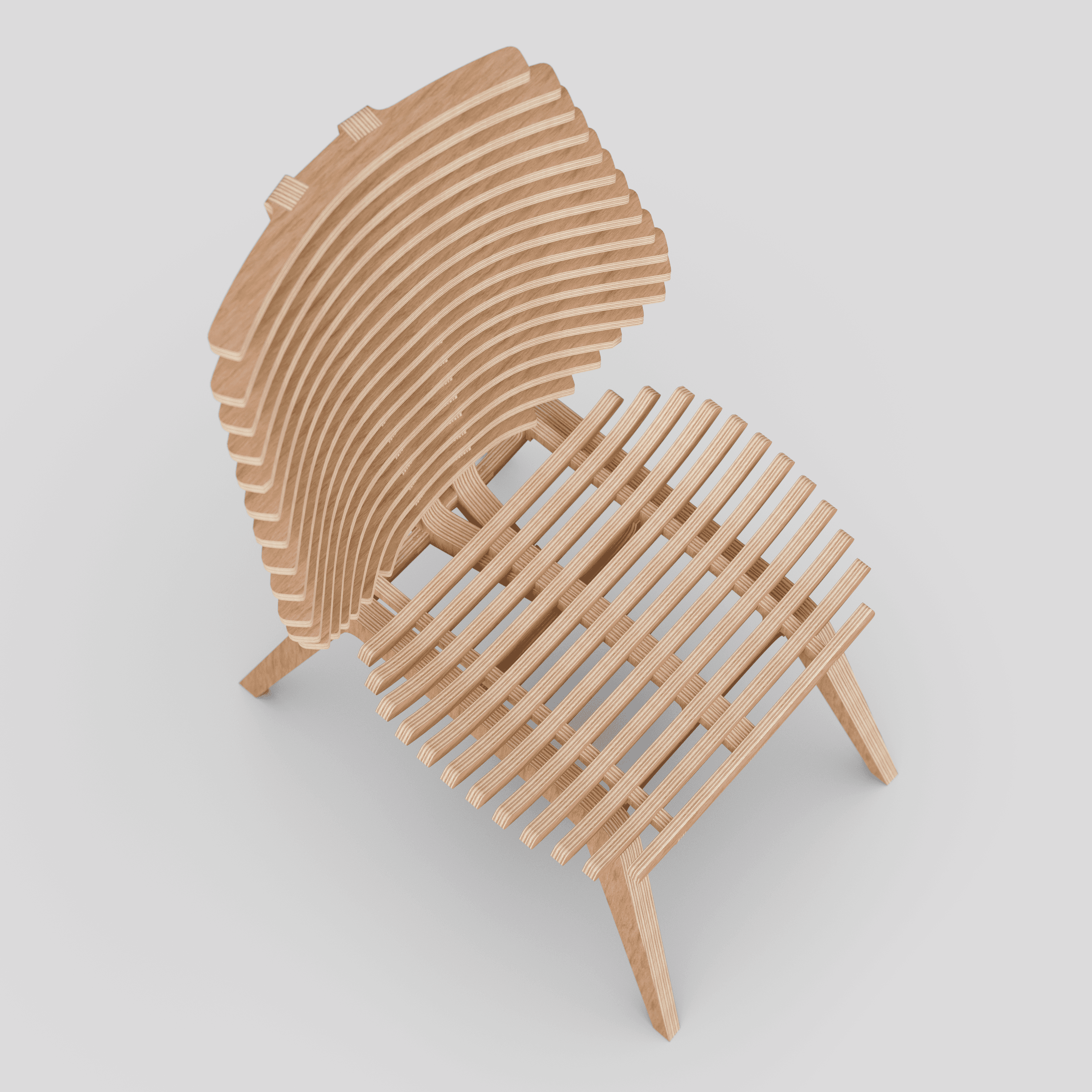




Top
